1. Definition
X1 setting means the signal enters the oscilloscope without attenuation;
X10 setting means the signal is attenuated by a factor of 10 before entering the oscilloscope.
-v211021
2. Probe Principle
The following diagram shows the equivalent circuit of the oscilloscope probe
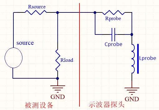
Rprobe is the input resistance of the probe, and the higher the value, the better. It divides the voltage with the circuit under test, making the measured voltage lower than the actual voltage. To avoid the impact of the probe’s resistance load, it is generally required that Rprobe be more than 10 times greater than Rsource and Rload.
Generally, the oscilloscope’s X10 probe input impedance is 10M; the X1 probe input impedance is 1M.
Cprobe is the input capacitance of the probe itself, also known as parasitic capacitance. This parasitic capacitance is the most important factor affecting the probe’s bandwidth, as it attenuates high-frequency components and slows down the signal’s rise time. Typically, high-bandwidth probes have smaller parasitic capacitance. Ideally, Cprobe should be 0, but this is not achievable in practice. Generally, the input capacitance of passive probes ranges from 10pF to several hundred pF, while high-bandwidth active probes usually have input capacitance ranging from 0.2pF to several pF.
Lprobe is the parasitic inductance of the probe’s lead. Typically, a 1mm probe’s ground wire has about 1nH of inductance; the longer the signal and ground wires, the greater the inductance value. The parasitic inductance and parasitic capacitance of the probe form a resonant circuit, which can cause high-frequency resonance and signal distortion when the inductance value is too large under input signal excitation. Therefore, during high-frequency testing, it is crucial to strictly control the lengths of the signal and ground wires to avoid ringing.
3. When to Use X1 and X10?
1. For unknown signals, it is best to use the X10 setting to avoid damaging the equipment.
2. When measuring circuits with larger internal resistance, such as crystal oscillators, use the X10 setting to obtain more accurate amplitude values, effectively increasing the input impedance.
3. For measuring power supplies and signal generator outputs with certain load capabilities, the X1 setting can be used. If the amplitude exceeds the oscilloscope’s input range, the X10 setting should also be used, as it serves to attenuate the signal.
4. For signal sources with higher internal resistance, the X10 setting should be prioritized, and the input sensitivity should be adjusted accordingly. If the measured signal is too small, the X1 setting must be used.
Original text from: Hardware Notebook