Drones consume a significant amount of energy during flight, especially for small devices. To address this issue, drone PCBA is designed to be more compact, denser, and faster, enabling more functions in a smaller space.

Signal Integrity Issues in Drone PCBA
From aerial photography to package delivery, drones are changing the way we live and work. But do you know the secret to making drones operate reliably?
High-speed printed circuit board assemblies (PCBA) are the heart of drones, determining the performance and reliability of the device. However, poorly designed PCBA can lead to signal integrity issues, such as signal reflection, crosstalk, and ground bounce. These problems can affect the stability and overall performance of the circuit.
Signal reflection can cause unstable flight in drones, even leading to loss of control due to receiving incorrect signals. Crosstalk can introduce noise into critical signals, interfering with sensor data or motor control commands. Voltage fluctuations caused by ground bounce can disrupt power delivery, potentially leading to unexpected shutdowns or failures. In summary, poor signal integrity can jeopardize the stability and smooth operation of drones.
Due to the small margin of error, circuit designers must understand the nuances of signal integrity in drone PCBA. This article will explain what signal integrity is, why it is crucial for high-quality PCB manufacturing, the symptoms of poor signal integrity, and how to use simulation tools to address these issues early in the PCB layout process.
Signal Integrity in Drone PCBA
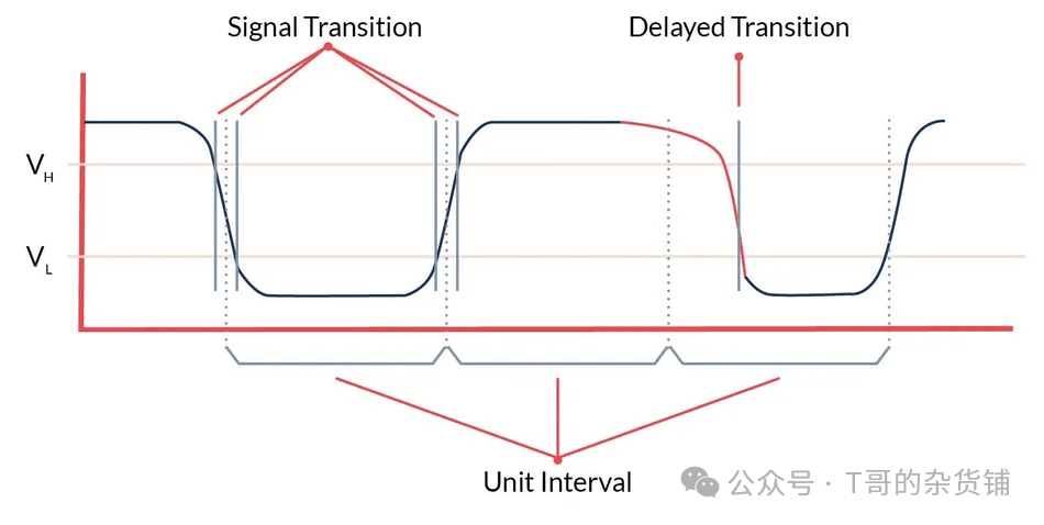
In digital systems like drones, information moves between components through signals, which essentially represent binary “0” or “1” as voltage levels. Signal integrity primarily focuses on the quality of the signals and the accuracy of timing during data transmission in the system.
Interconnect devices are the conductive paths for these signals from source devices to destination devices. They include everything in the path: packages, solder balls, connectors, PCB traces, cables, and component leads.
The main challenges to signal integrity arise from the physical characteristics of interconnect devices, such as resistance, capacitance, and inductance. Resistance in interconnect devices can lower voltage levels, thereby weakening the signal by the time it reaches the receiver. Additionally, at high frequencies, capacitance and inductance in interconnect devices can lead to crosstalk and electromagnetic interference (EMI).
Therefore, in drone PCBA design, interconnect devices are complex frequency-dependent parasitic elements. Under certain conditions, their characteristics can distort or weaken signals, especially during high-speed data transmission, posing challenges to maintaining signal integrity.
Common Signal Integrity Issues in Drone PCBA
The quality of signal integrity in drone PCBA directly affects the bit error rate during data transmission. In turn, this impacts the performance of the drone. Common causes of poor signal integrity include:
-
Crosstalk: Occurs when the signal from one conductive path unintentionally affects another conductive path, primarily due to capacitive or inductive coupling in the transmission path. Crosstalk can lead to incorrect logic switching on static traces and alter timing on active traces.
-
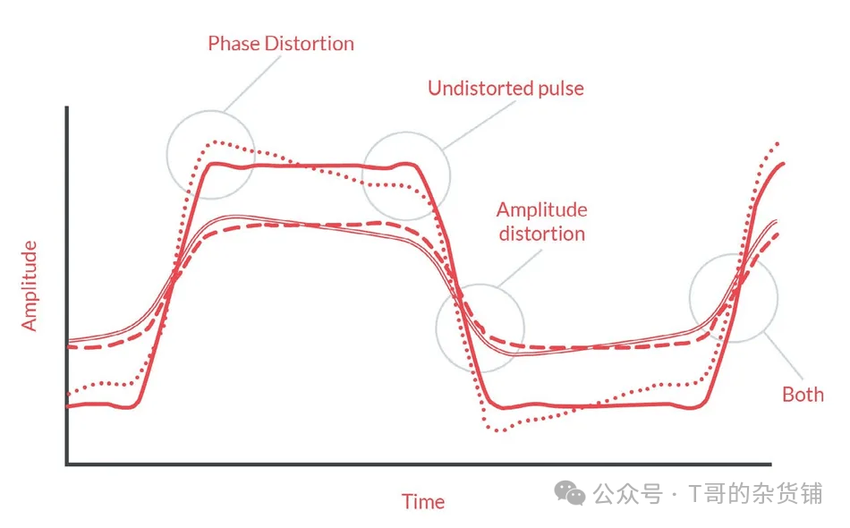
Reflection: Occurs when current with a specific direction in a PCB trace encounters an impedance change in the transmission path. This mismatch can cause part of the signal to bounce back, interfering with the input signal. Reflection can lead to erroneous clock triggers, increased jitter, and more unwanted radiation from the PCB, all of which degrade drone performance.
-
Ground Bounce: Sometimes referred to as synchronous switch noise (SSN) or delta-I noise, it refers to temporary spikes in ground voltage within the circuit board. This is caused by multiple signals turning on or off simultaneously, resulting from the inductance in the circuit path or component leads. It can lead to signal distortion, reading errors, and slower data transmission.
Design Challenges in Drone PCBA Leading to Poor SI
Flight consumes energy, especially for small devices. This is primarily due to the challenges posed by miniaturization of the aircraft. The smaller the size, the less power the motors have, the greater the friction from mechanical parts like gears and bearings, leading to lower efficiency, and the impact of air resistance becomes more significant due to changes in airflow characteristics (Reynolds number).
To address these issues, drone PCBA is designed to be more compact, dense, and fast, enabling more functions in a smaller space. They also use multilayer PCBs to improve routing. However, this necessary design approach also makes them more susceptible to signal integrity issues.
Here are some design challenges in drone PCBA:
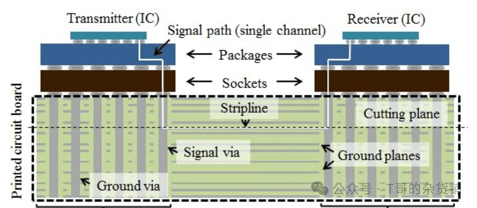
High-speed multilayer printed circuit boards: Drone multilayer PCBs designed for high-speed signal transmission include vias that connect different layers of the printed circuit board. At high frequencies, these vias can introduce impedance mismatches, leading to signal reflections.
Layer Count and Thickness: The complexity of drone PCBA often requires a higher number of layers, which increases the thickness of the PCB. This thickness can increase via height, increase insertion loss, and reduce signal strength and quality.
Miniaturization and Crosstalk: Drone PCBA employs dense packaging and miniaturized designs, amplifying the effects of crosstalk. Due to the close proximity of traces, the likelihood of signal interference between adjacent traces increases.
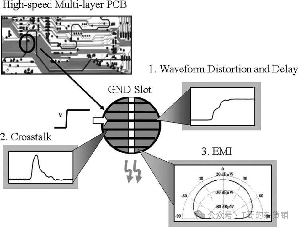
Heterogeneous Systems: Drones are heterogeneous systems, meaning they consist of various devices, each with its own power, current, speed, and noise requirements. To meet these requirements, PCBA layers are often split into independent power supplies. While split planes can improve the quality of power/ground networks, the slots introduced for split planes can lead to poor radiation emissions and reflections.
Symptoms of Poor Signal in Drone PCBA
When the signals on a drone’s circuit board (PCBA) are poor, there may be subtle clues indicating that the design may not be robust or reliable. The main symptoms include:
-
Failed Compliance Testing: If the drone does not meet specified standards, it may indicate signal issues.
-
Problems After Component Replacement: The drone initially performs well, but issues arise after changing chip suppliers or PCB manufacturers.
-
Environmentally Sensitive: If the drone’s circuit board performs poorly under different power supplies or temperatures, this may indicate poor signal integrity. A good design should remain stable under various conditions.
-
Inconsistent Laboratory and Field Performance: If it runs well in the lab but is unreliable in real-world environments, this is a typical symptom of signal issues.
How to Address
While it is impossible to completely eliminate all signal issues caused by crosstalk and reflection in drone circuit boards, there are several good practices that can significantly reduce these problems.
Reducing Crosstalk
-
Separate components and input/output interfaces, keeping them away from problematic areas.
-
Route critical lines separately, avoiding parallel runs.
-
Minimize the distance between signal lines and ground lines.
-
Ensure impedance matching for critical signal lines.
-
Avoid using shared return pins in packages and connectors.
Reducing Reflection
-
Match and terminate according to the characteristic impedance of the transmission line to prevent mismatches.
-
Minimize the length of vias.
-
Utilize stacked devices to place traces close to reference planes, optimizing signal return paths.
-
Select appropriate via sizes. Larger diameters increase impedance discontinuity, leading to increased reflection and insertion loss; longer vias may reduce reflection but increase insertion loss.
90-Degree Turns in Transmission Paths
When traces connect to components, they may need to turn. At high frequencies, a 90-degree sharp turn can cause signal reflection. Typically, two 45-degree bends are used to alleviate this instead of a sharp turn.
Differential Pairs
When using differential lines in drone circuit board design, the two lines should remain symmetrical. Distances and lengths should be equal. If they are not, issues like ground bounce can occur. To address length differences, a herringbone pattern can be added near the start of the shorter line. This way, signals across the entire circuit board can remain synchronized.
FR-4 Weaving Effect
When routing signals on substrates like FR-4, weaving effects can occur, where one line may be on the fiber and another on the epoxy. These materials have different dielectric constants, leading to discrepancies in electrical length and simulation predictions, especially in differential lines and buses at frequencies above 5 GHz.
To mitigate this, routing in a shallow zigzag pattern of about 10 degrees can balance variations by crossing fibers and epoxy. Another method is to use isotropic substrates like Rogers TMM, which, while more expensive, do not have this issue.
Simulation and Verification
Simulation techniques can effectively identify signal issues in drone circuit boards. Once identified, layout optimizations can enhance performance, and appropriate termination methods can mitigate the impact of signal issues.
Simulation tools can focus on signal integrity early on, developing high-performance, high-reliability, and cost-effective products. This proactive approach accelerates time-to-market, ensures competitive advantage, and reduces the need for extensive prototype debugging, allowing for quicker entry into future projects.
Simulation tools can be categorized into three types:
-
Mathematical Tools: These tools model digital transmission systems using equations and graphs. Tools like Matlab, MathCad, and Mathematica provide a theoretical approach to studying signal behavior.
-
Analog Simulation Tools: These tools create and simulate circuit schematics. Tools like Spice, HSpice, and PSpice are well-known for their schematic-based analysis.
-
Specialized SI Simulation Tools: These tools are designed specifically for high-speed digital circuit analysis, supporting pre-layout exploration and post-layout verification. They can assess signal quality and whether performance margins meet various interfaces (including DDR and high-speed serial channels). Examples include HyperLynx and Cadence.
Conclusion
Signal integrity issues can lead to product failures or component damage, often resulting in failures occurring after the product is in use rather than during testing. This can lead to increased costs and loss of customer trust.
To address signal integrity issues, it is essential to first understand the root causes. Then, utilize all available tools to find and examine the best solutions.
Through early effective design and simulation, performance and cost can be balanced before it is too late, saving time, reducing risks, and lowering costs.
ClickFollow,Make Friends THE END
The content represents the author’s personal views and may not be reproduced without authorization.
The opinions and data in this article are for reference only; any commercial use is at your own risk.
If there are any violations or infringements, please message for deletion.
Reposting, liking, and showing love are all encouragement!