
Source:Medical Equipment
Author:Huang Jian
The ultrasound diagnostic device, as a precise and valuable clinical diagnostic medical equipment, is currently widely used in various hospitals. Although there are numerous brands and model specifications, the working principle is basically the same, which is that the instrument emits ultrasound waves through the probe. The ultrasound waves reflect off the various tissue interfaces in the human body, and due to the different reflection waves from each tissue, the probe receives these reflected waves containing characteristic information of the tissues, which are then sent back to the main unit for signal reconstruction and image processing, finally storing and displaying the image on a monitor. Based on the principles and daily maintenance, we can roughly divide the ultrasound diagnostic device into the following components: probe, main unit, power supply, monitor, and peripherals.
01
Probe

The probe is one of the core components of the ultrasound diagnostic device and is expensive. Due to frequent use, it is the most easily damaged part. The probe generally consists of a transducer, acoustic lens, housing and sheath, cables, and other accessories. In addition, three-dimensional and four-dimensional probes also have a drive motor component. In general, one can initially determine if there is a fault by swapping probes or by listening to the probe to see if it is making operational sounds.
02
Transducer
The transducer is an important part of the probe, also known as the crystal or acoustic head, made of piezoelectric ceramics. Its task is to convert electrical signals into ultrasound signals for emission and to convert the received ultrasound signals back into electrical signals. Prolonged use of the transducer can cause natural aging, and improper use or impacts can also damage the crystal, leading to issues such as reduced images, shadowing, black stripes, interference, loss, or blind spots. If there are obvious dark channels in the ultrasound image, after excluding faults in the cables and acoustic lens, one can generally preliminarily determine it as a crystal fault, which is often caused by short circuits in the chips. The short circuit of the chip can be judged by measuring the power supply voltage of the chip. If the power supply voltage of a certain chip or chip group is lower than that of others, it can be determined that there is a short circuit in that chip or chip group. Replacing the corresponding chip or chip group can restore the probe’s previous characteristics and eliminate the interference.
03
Acoustic Lens
The acoustic lens is a gel-like special material that contacts the human body at the top of the probe. Long-term use can cause natural wear, scratches, cracks, corrosion, adhesive failure, and bubbling, especially corrosion caused by coupling agent entering the layer below, which can cause artifacts, blind spots, and more severely, damage to the probe crystal or leakage, endangering the patient’s health. Therefore, if such situations occur, timely repair or replacement should be carried out to ensure safety and avoid greater losses. The fault of the acoustic lens is acoustically manifested as local shadows on the ultrasound image, but if appropriate pressure is applied to the shadow area, the shadow will disappear. This method can quickly distinguish whether the issue is with the acoustic lens or the acoustic head.
04
Housing and Sheath
The housing is the outer shell of the acoustic head, and damage is usually caused by accidents. Once the outer shell of the acoustic head is cracked, it can lead to coupling agent seeping into the probe, causing oxidation and corrosion of the acoustic head chip. Additionally, three-dimensional and four-dimensional probe housings contain cooling oil for the cooling motor, and a cracked housing can lead to liquid leakage. Therefore, faults in the acoustic head housing also need to be repaired promptly. The sheath is a rubber sleeve that reinforces the connection between the probe and the cable, preventing the cable from bending at right angles. If damaged, it can compromise the quality of the shielding layer, causing image interference and blurriness. If the cable breaks, it can severely affect the ultrasound image, and in severe cases, leakage can occur.
05
Cable
The cable consists of hundreds to hundreds of multi-core high-shielding cables with high quality requirements, generally including signal lines, ground lines, control lines, and power lines. The voltage of the ultrasound transmission and reception signal lines during emission is over one hundred volts. Faults in the cable can lead to system crashes, black channels, interference, probe recognition failures, and ghosting. Cables, especially those near the acoustic head, can become damaged or even break due to prolonged bending. When such faults occur, it is generally necessary to cut and reconnect the faulty section of the cable, and sometimes the entire cable needs to be replaced.
Fault Phenomenon: A GE VOLUSIONE8 ultrasound machine shows severe interference in the sector image on the monitor, with weak echoes and a screen full of snowflake-like spots flashing intensely. Analysis and Repair: Since the sector image has a problem, the first thought is the probe’s fault, as the sector images are directly emitted and received by the probe. Upon inspecting the probe, it was found that the cable below the sheath had exposed shielding due to frequent friction, revealing the internal cables. The shielding wire was stripped, and the seemingly broken cable was resoldered, covered with heat shrink tubing, the shielding layer was soldered, and the cable was wrapped with insulating tape. After testing, the fault was eliminated.
06
Main Unit
Currently, the main unit of the ultrasound diagnostic device generally includes a frontend part and a computer control part. The frontend part typically consists of pulse generation, control circuits, ultrasound signal reception and processing circuits, digital scanning conversion devices, and digital image processing circuits. Damage to these components can cause the probe to malfunction, sector images to be absent, interference in sector images, artifacts, and various other faults. Generally, the fault range can be determined by swapping or unplugging components, and fault codes and circuit board indicator lights can also provide preliminary fault location hints. The computer control part usually consists of a high-performance PC or industrial motherboard, and the principles are similar to those of general computers, with common faults occurring in hard drives, graphics cards, memory modules, and system software.
Fault Phenomenon: An Aloka F37B ultrasound machine reports an error upon startup, indicating a missing file and unable to enter the normal working interface. Analysis and Repair: The missing file prompt generally indicates a hard drive fault. The first attempt was to repair the file; however, another system fault was reported. After swapping the motherboard and hard drive, it was confirmed that the hard drive was faulty, and after replacing it with a new hard drive, the fault was eliminated.
07
Power Supply
The function of the power supply module is to convert mains electricity into various working voltages required by each part of the machine; the power supply is also a common fault area in ultrasound diagnostic devices due to fluctuations in the power grid and high power consumption and temperature, resulting in a high failure rate. The manifestations of power supply faults are varied, often presenting as functional failures of the entire system or a specific part of the system. Interference introduced by the power supply can also prevent the instrument from functioning normally. When the fault range cannot be determined, the power supply’s operation is generally checked first. Particularly, high-power, high-current, and high-heat components such as rectifier bridges, voltage regulators, and field-effect transistors are prone to burning out and being damaged.
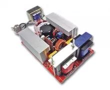
Fault Phenomenon: A Philips HD15B ultrasound machine shows no response when the power button is pressed and cannot be powered on. Analysis and Repair: The initial suspicion was a power supply fault. Since the HD15’s power system is divided into main power and computer power, after the mains is connected to the main power, only one group of 110V AC output is provided. This voltage is supplied to the computer power through the communication cable connected to the computer. After the computer starts, the interface board (PCI0) installed inside the computer sends a startup signal to the main power through the communication cable via the ACB board, allowing the other voltage groups of the main power to start, which supplies power to the front end of the HD15, external printer, and LED display. After measuring, the input of 220V was normal, and the output of 110V was normal, but the computer did not start, leading to suspicion of the communication cable. After replacing the communication cable, the fault was eliminated.
08
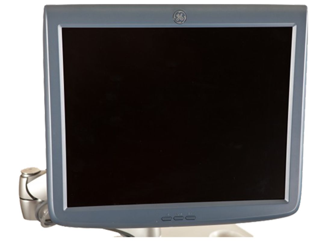
Monitor and Peripherals
The monitor operates on principles similar to ordinary computer monitors, but with higher resolution. Faults often occur in the scanning part, with the highest failure rate in the line scanning section. Similar to the power supply part, when the line scanning section operates normally, it is under high voltage and high current conditions, consuming more than half of the monitor’s total energy. During normal operation, it has a series of heating components, such as line output tubes, line output transformers, and line correction coils. Poor heat dissipation can cause these components to overheat and fail or cause circuit boards to detach. Peripherals such as keyboards are also similar to ordinary keyboards but with more keys. Poor contact is the most common issue, usually caused by dust, contact oxidation, or damage to the conductive rubber in touch switches.
The above is the basic structure of the ultrasound diagnostic device and some repair ideas. For engineers in hospitals, mastering the basic principles and structure of color ultrasound undoubtedly plays a significant role in maintenance. Of course, maintaining and preventing faults in the instrument is also very important. Since color ultrasound is a high-precision instrument, it has higher requirements for working conditions, such as controlling the room temperature around 25°C; humidity control between 50% and 60%; a stable power supply to prevent voltage fluctuations; proper grounding to prevent interference and leakage, with a grounding resistance of no more than 2Ω. This requires us to do a good job of heat and moisture prevention, regularly dusting the instruments, cleaning at least once every six months, and limiting continuous operation time to no more than 4 hours, with mechanical fans sweeping the probe for 10-15 minutes of continuous use before stopping. This can greatly reduce the maintenance rate of the ultrasound machine and extend the instrument’s lifespan, providing greater benefits and economic value for hospitals.
Statement
Previous Selections