Contact WeChat: x274529
LoRa is short for Long Range, a type of wireless communication technology characterized by long distance and low power consumption. The data rate is relatively low, and it can be considered as the physical layer implementation in network communication. The corresponding products for LoRa are transceiver chips, such as Semtech’s SX1272/SX1276, which mainly handle binary data streams. LoRaWAN is a protocol standard based on the LoRa physical layer transmission technology, primarily focused on the MAC layer, corresponding to the data link layer (MAC layer) in the OSI seven-layer model. LoRaWAN eliminates hardware incompatibility while achieving features such as multi-channel access, frequency hopping, adaptive data rate, channel management, timed transmission and reception, node access authentication, data encryption, and roaming.
Common LoRa modules available on the market typically implement only the physical layer communication. To achieve LoRaWAN functionality, software is required to implement the LoRaWAN protocol, and a gateway is also needed for network communication.
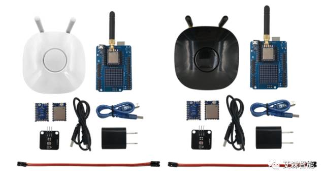
Today, we will experience the LoRaWAN Dev Kit from AISenz, which is a complete LoRa kit that includes a small LoRa gateway, two different types of LoRa nodes, and accompanying sensors, allowing for a full experience of LoRa IoT functionality.
1. Bill of Materials and Supporting Documentation
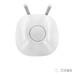
NanoGateway Dual-Band MultiSF
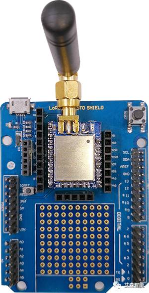
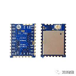
LoRaWAN Shield + AI78L
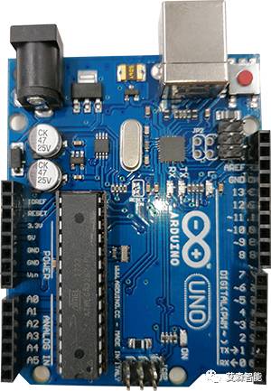
Arduino Development Board
2 x AI78S
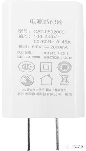
1 x Mini USB Cable
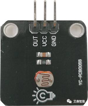
1 x Light Sensor
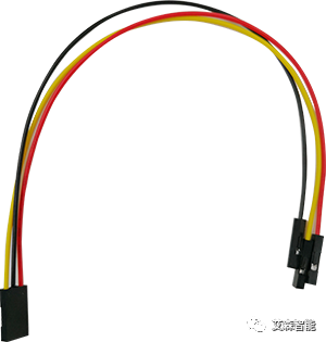
1 x 3 Pin Dupont Line
Gateway available in two colors
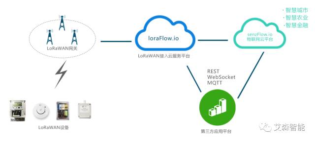
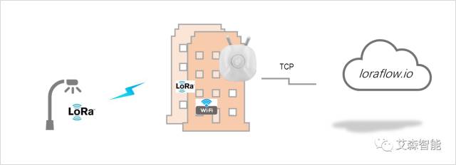
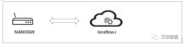
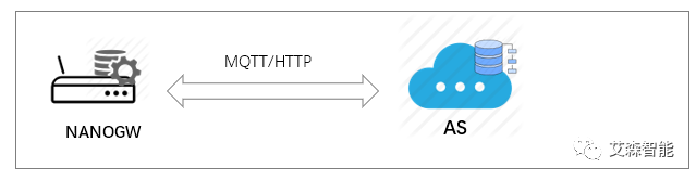
Using the AISenz development kit as an example, we will introduce how to quickly set up a LoRaWAN network. First, let’s take a look at the overall network architecture:
To set up the network, please follow these steps:
1. Create an IoT cloud platform account
2. Configure the NanoGW gateway to connect to the cloud platform
3. Connect the Arduino development board and module to the cloud platform
4. Collect light sensor data and upload it to the cloud
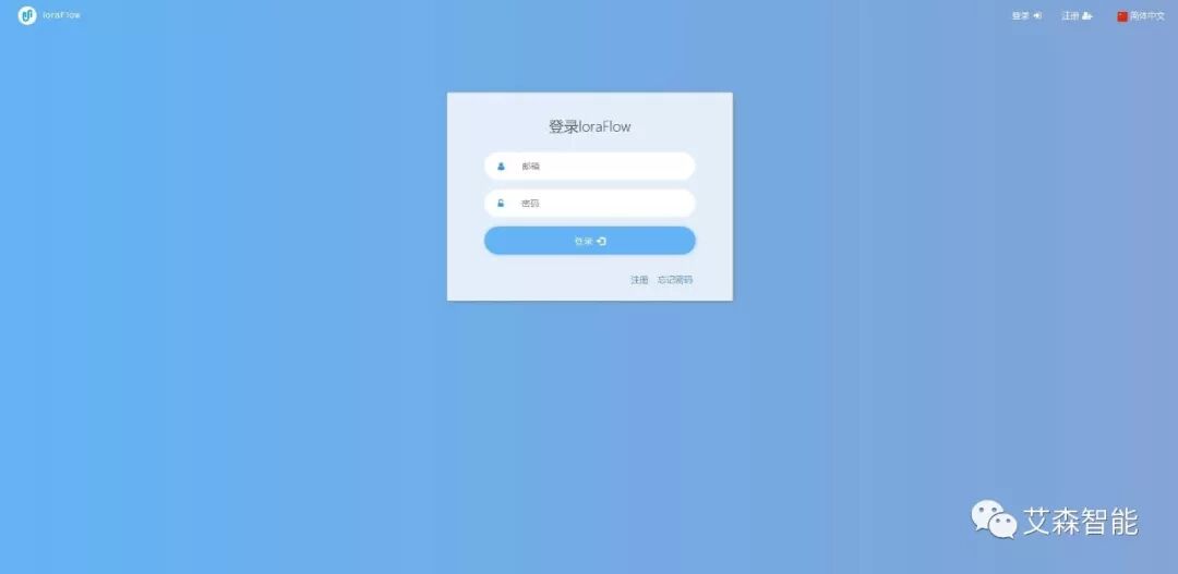
2. Create an IoT Cloud Platform Account
Register an account at https://www.loraflow.io/login to use the AISenz LoRaWAN IoT cloud platform.
Figure 1 Cloud Platform Login
3. Configure the NanoGW Gateway to Connect to the Cloud Platform
AISE001E is a multifunctional LoRaWAN indoor gateway (NanoGW) that supports dual-channel LoRa and WiFi for downlink data and supports WiFi, Ethernet, or cellular network for uplink data.
The standard version of AISE001E can seamlessly connect to the loraflow.io cloud platform and loraCube private cloud products, including the following sub-series:
—AISE001E: Supports WiFi and Ethernet uplink data
—AISE001E4G: Supports WiFi, Ethernet, or cellular uplink data
3.1 NanoGW Supports Web-Based Parameter Settings:
First, connect to the gateway device. Users can connect via WiFi or Ethernet.
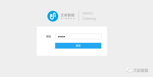
The gateway is factory-set to WiFi hotspot mode, with the hotspot name “AISENZ-NANO-XXXX” (labeled at the factory). Connect to the hotspot, and the IP address is 192.168.100.1. Users can access the gateway device through their computer browser at http://192.168.100.1:8080, with the login password: admin, to enter the configuration interface.
Login Interface
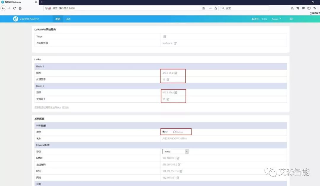
Configuration Interface
Users can also connect to the gateway via Ethernet. The gateway is factory-configured with a static IP address, accessible at http://192.168.99.1:8080. Once the user completes the configuration and restarts, this address will become invalid.
3.2 Set Network Parameters
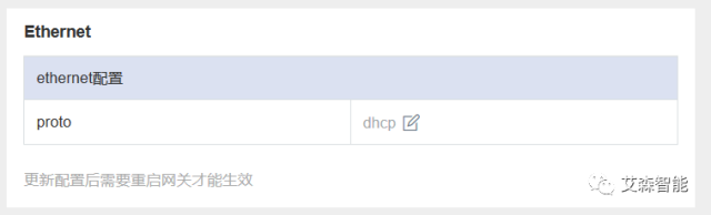
Configure the Ethernet interface parameters. The Ethernet port can be configured for DHCP or static IP. For enhanced gateways with embedded web servers, it is recommended to configure as a static IP.
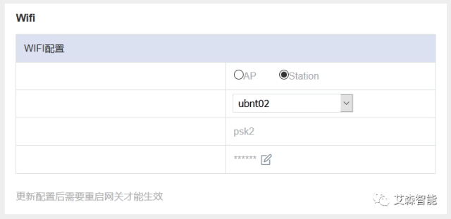
Configure the WiFi interface parameters. If WiFi is used for downlink data, it can be configured in AP mode; otherwise, configure in Station mode.
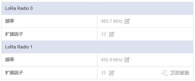
Configure the LoRa wireless parameters. Supports setting two LoRa channel parameters, including frequency points and spreading factors. Radio0 and Radio1 frequency configurations can be the same or different. The spreading factor range is from SF7 to SF12.
Note: The reliability of multi-SF (MultiSF) reception on the same frequency is easily affected by the environment. In commercial deployments, it is recommended to configure as different frequencies with the same SF.
After configuration, restart the gateway. If using a public cloud, directly skip to 3.4 to connect to the cloud.
3.3 Set Server Parameters
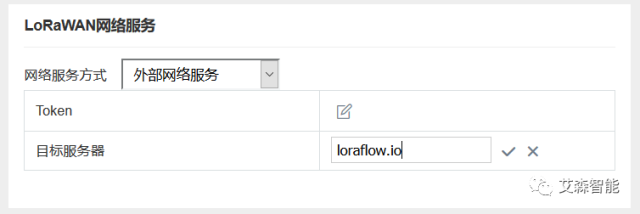
Standard version gateway server parameter settings
The target server can be the public cloud loraflow.io or the private cloud loraCube.
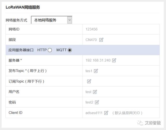
Enhanced version gateway server parameter settings
Local network service settings include region parameters (frequency band Band) selection and application server interface configuration.
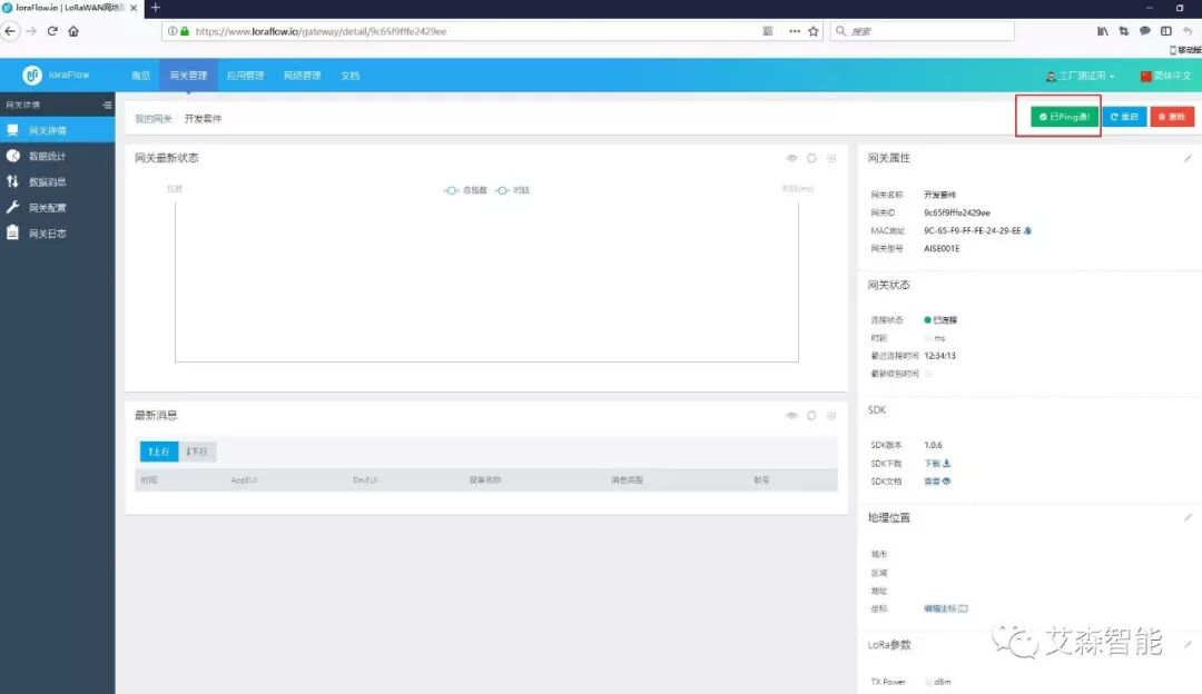
3.4 Gateway Access via Registered Account from Step 2
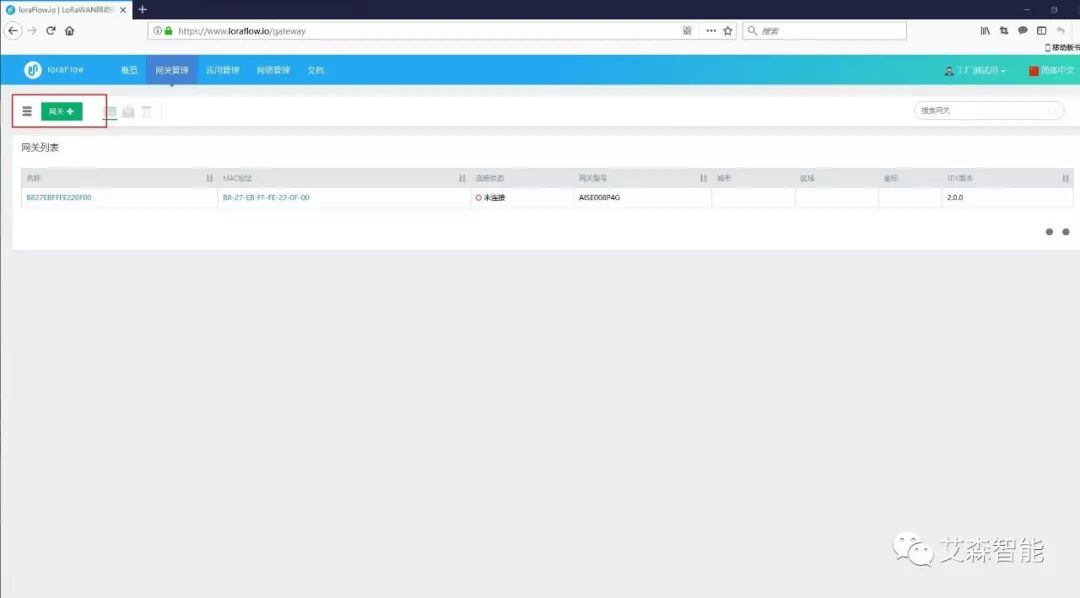
Go to https://www.loraflow.io/login. Add the gateway.
Figure 5 Add Gateway
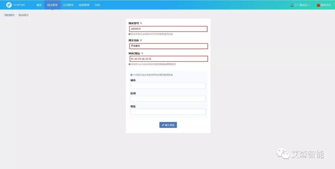
Figure 6 Add Gateway MAC Address
PING success indicates successful network access.
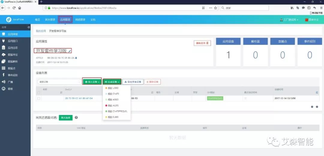
3.5 Add Applications and Devices
Create an application on the cloud platform
Add Device
Add devices or generate devices under the application
4. Connect Arduino Development Board + Module to Cloud Platform
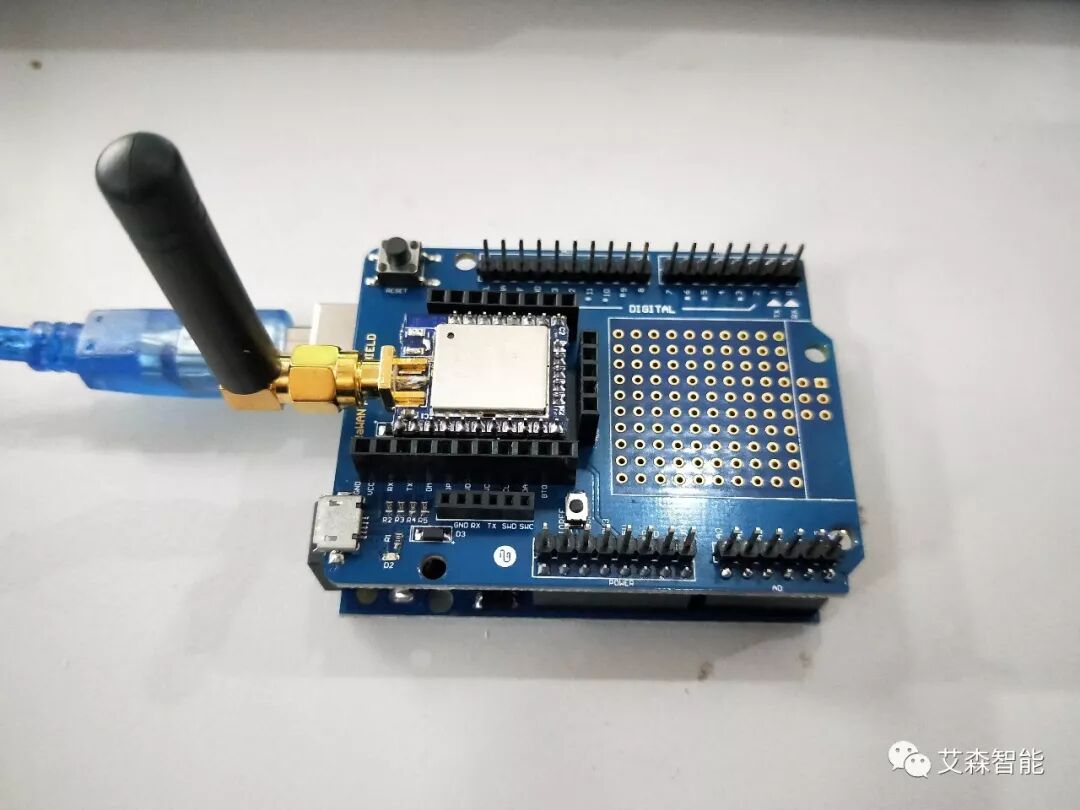
4.1 Connect Arduino UNO to the computer via USB;
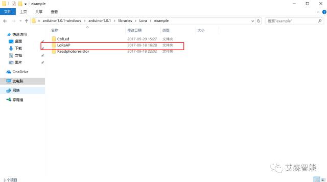
Before starting to learn Arduino, you need to install the Arduino Software (IDE) to control your development board; the AISenz LoRaWAN module is directly inserted into the Arduino UNO baseboard, and the module should be installed as shown in the figure. Download the accompanying LoRaAP version.
Figure 11 Module + Adapter Board + Arduino
AISenz accompanying program
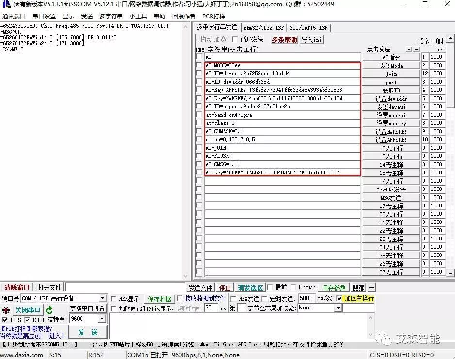
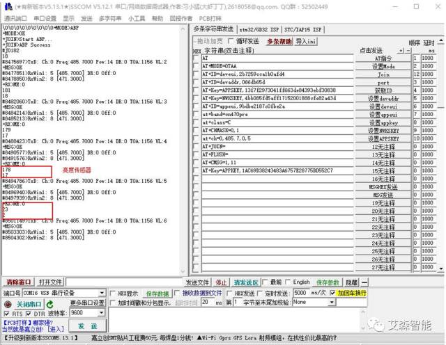
4.2 Open Serial Assistant to Configure the Module
Figure 13 Configure Module
Through the added device on the cloud platform (Step 3.5), configure the module device EUI, device address, frequency band, terminal type, NwSkey, AppSkey, appeui, etc., to achieve data transmission from the module, completing the entire link setup.
By sending AT+CMSG=1,11, the data is transmitted, where 11 is converted to ASCII code 3131, successfully joining the network.
Figure 14 Data Transmission
If the above figure is achieved, the LoRaWAN setup is complete.
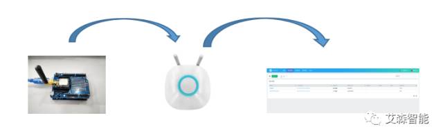
5. Collect Light Sensor Data
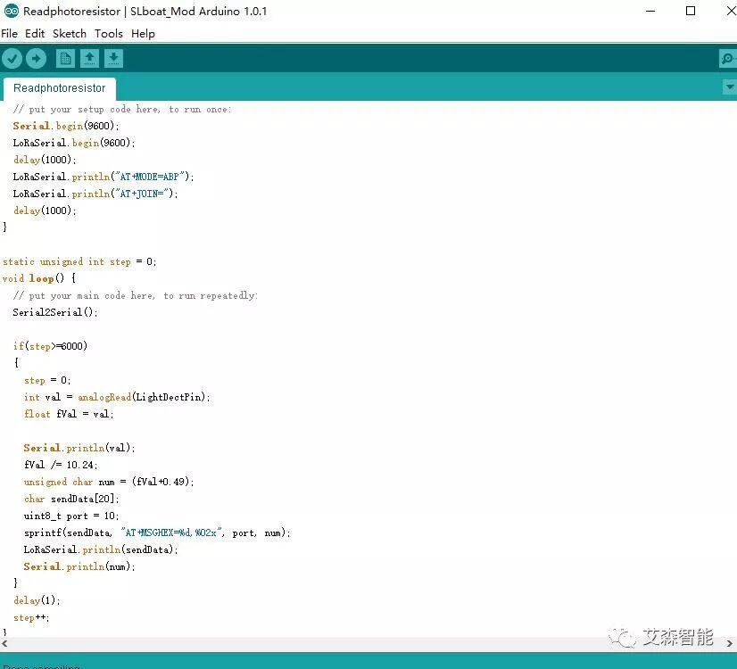
Using the LoRaWAN module, collect light resistance data and upload it to the gateway, using Arduino to read the brightness sensor’s AD value and send it to the module via serial, then send AT commands, allowing users to observe data in the cloud, applicable for reading data from electric meters, temperature, water meters, etc.
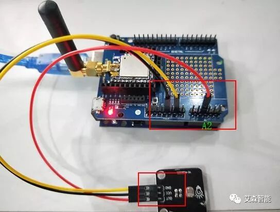
5.1 Connect USB to PC, connect the light resistance module to the Arduino expansion board, VCC to 5V, GND to module GND, OUT to A2, connected as shown:
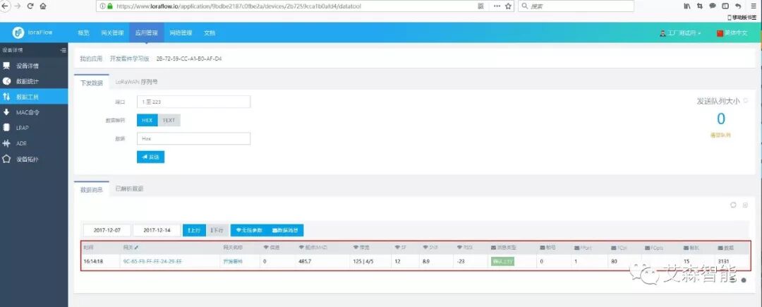
5.2 Download the AISenz accompanying program, observe the brightness sensor value via serial, and the data can be intuitively read in the cloud.
Accompanying Arduino reading program
Serial Assistant Display
Cloud Data
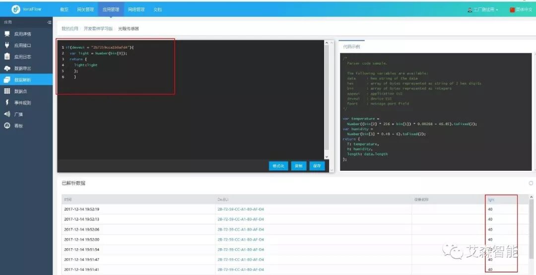
5.3 Data Parsing
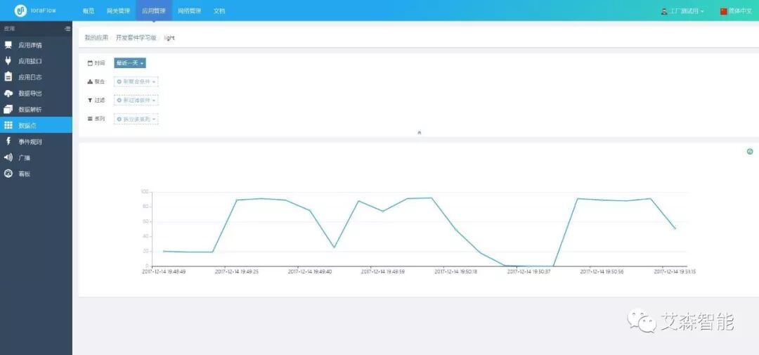
By reading the corresponding bits in data parsing, the corresponding results can be output, and the data uploaded by the user will be presented to the user in a visual form, as shown in the figure below:
In addition, there is corresponding time information for the data, which will be stored in the cloud, and users can export it in JSON or CSV format for later analysis.
Overall, the AISenz LoRaWAN Dev Kit is a great kit. In addition to providing two LoRa nodes and some simple sensors, it is more important to provide a LoRa gateway, as a LoRa application without a gateway cannot be considered complete. The official price for the standard version kit is 699 RMB, which is quite reasonable compared to other similar products domestically and internationally. The accompanying software examples are also quite complete, covering everything from LoRa communication to complete IoT applications, providing excellent guidance for users to quickly get started and for later product-level applications.
Source: AISenz
LPWAN Industry Alliance Organized and Released
This is a public account with a voice…
Long press, scan the QR code, and follow us!