
1. What Exactly Is PLC? Think of It as an “Industrial Butler”
PLC (Programmable Logic Controller) is like the “smart butler” of a factory, responsible for receiving sensor signals (such as high temperature or machine jams) and controlling equipment actions based on pre-set programs (like shutting down machines or activating alarms).
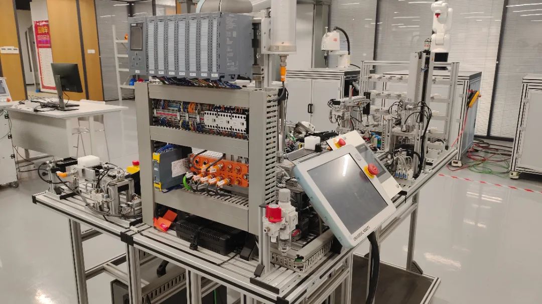
For example, the automatic temperature control function of your air conditioner is actually a simplified PLC system: the temperature sensor is its “eyes,” and the logic controlling the compressor’s start and stop is its “brain.”
Common Misconceptions for Beginners:
-
Thinking PLC = Large Calculator
In reality, PLC is more like a “condition reflex expert”; it is not good at complex math but can respond to emergencies in milliseconds.
-
Believing Ladder Diagrams Are Incomprehensible
Actually, ladder diagrams are similar to household circuit diagrams, with the power source on the left, the load on the right, and switches controlling the circuit.
2. Dissecting PLC: Let’s Look at Its “Vital Organs”
1. The Four Core Components
-
CPU (Central Processing Unit)
: Equivalent to the brain of the butler, capable of processing thousands of commands per second.
-
Input Module
: The “sensory system” of the butler, receiving buttons, sensors, etc. (like emergency stop button X0).
-
Output Module
: The “hands and feet” of the butler, controlling contactors, solenoid valves, etc. (like motor Y1).
-
Power Supply Module
: Powers the entire system; be sure to add an isolation transformer; I once burned out the entire input board because I didn’t use isolation!
Hardware Fun Facts:
- Transistor output PLCs are 10 times faster than relay types but can only handle DC loads.
- Modular PLCs have expandability comparable to LEGO blocks; I’ve seen configurations with 32 modules attached!
3. PLC’s “Work Schedule” — Scan Cycle
The workflow of a PLC is like an assembly line in a factory:
-
Inspection Phase
(Input Sampling): Checking the status of all sensors one by one (completed in 0.1ms)
-
Thinking Phase
(Program Execution): Judging what to do based on ladder diagram logic (speed comparable to lightning)
-
Execution Phase
(Output Refresh): Sending the calculated results to the actuators (like starting the motor)
Lessons Learned:
- Too long programs can slow down the scan cycle; once, a project delayed machine actions by 3 seconds because I added 200 extra steps!
- Emergency signals should use interrupt functions, just like when your doorbell rings, the butler must open the door immediately instead of waiting to finish chores.
4. A Step-by-Step Guide to Understanding Ladder Diagrams
Take the simplest motor start-stop circuit as an example:
1|--[X0]----[Y0]--|  (Start button pressed, motor runs)
2|--[Y0]----|     (Self-locking hold)
3|--[X1]----|/|---(Stop button opens the circuit)
4
Debugging Tips:
- Use the “online monitoring” feature to view the status of contacts in real-time; it’s much more reliable than guessing
- Break complex programs into segments for debugging; I prefer to use indicator lights to verify logic before actual loads
5. Selection Pitfall Guide
1. How to Count Points?
- Input Points: All sensors + buttons + switches
- Output Points: Number of actuators × 1.2 (to leave a margin) Last year, I took on a project where the client said they only needed 8 output points, but after upgrading the equipment, they needed 12, almost causing a disaster!
2. Brand Selection Mysteries
- Use Japanese brands (Mitsubishi, Omron) for small devices; they offer good value for money
- Choose German brands (Siemens) for complex controls; they are powerful but expensive
- Domestic brands (Xinjie, Delta) are suitable for projects with limited budgets
6. Eight Important Notes for On-Site Debugging
-
Power Off Before Wiring!
I have experienced the painful lesson of burning three output modules due to live operation
- Analog signals must have shielding; otherwise, interference will make you question your sanity
- Replace backup batteries regularly; once, the program was lost after a power outage, causing a 6-hour production line stoppage
- Ground wires cannot be neglected; I have seen the most outrageous interference where the PLC controlled lights flickered randomly
- Program comments should be detailed; after three months, you might not recognize the code you wrote
- Use forced output functions with caution; I almost triggered an oil leak by forcing the hydraulic station to start
- Keep 20% memory space free; you’ll understand how important this is when modifying the program later
- Important parameters should have power-off retention; don’t let the device reboot and become a “dummy”
7. Classic Application Case Studies
Case 1: Automatic Packaging Machine Control
-
Input Signals
: Material arrival sensor, emergency stop button
-
Output Control
: Conveyor motor, sealing machine, coding machine
-
Core Logic
:
- Delay 0.5 seconds to start sealing after material arrives
- Allow coding only after the sealing temperature reaches the set value
- Immediately cut off all outputs and trigger an alarm in case of a fault
Case 2: Automated Parking Garage Control System
-
Difficulties
: Need to handle vehicle detection, lift positioning, and safety interlocking simultaneously
-
Tips
: Use shift registers to track parking space status, and high-speed counters for precise positioning
8. Common Fault Troubleshooting Manual
| Fault Phenomenon | Possible Causes | Troubleshooting Methods |
|---|---|---|
| No response from input points | Loose wiring/sensor damage | Measure voltage with a multimeter → Check program → Replace module |
| Output points malfunctioning | Poor grounding/electromagnetic interference | Add magnetic ring → Check shielding → Isolate power supply |
| Communication interrupted | Incorrect baud rate/cable too long | Use terminal resistors → Replace with twisted pair |
| Program lost for no reason | Dead battery/electromagnetic interference | Immediately back up → Replace battery → Add shielding |
9. Practical Suggestions for Beginners
-
Start Practicing with Light Control
- Day 1: Control the indicator light on and off using a button
- Day 3: Add a flashing function (timer application)
- Day 7: Achieve multi-level interlocking control
-
Modify Household Appliances
- Add an automatic water change system to the fish tank (float switch + water pump)
- Create a smart drying rack (rain drop sensor + motor control)
-
Disassemble an Old PLC
- Familiarize yourself with real components (relays, optocouplers, power transistors)
- Practice module disassembly and assembly (be careful of static!)
What bizarre faults have you encountered while debugging PLCs? We’re waiting for your comments!

ZHINANCHE
Guidance Vehicle Robot Training Courses Are Now Open!
In-depth and Easy to Understand | Beyond Basics
If You Want a Good Job,Come to Guidance Vehicle!
From Learning to Employment,Just Follow Guidance Vehicle!
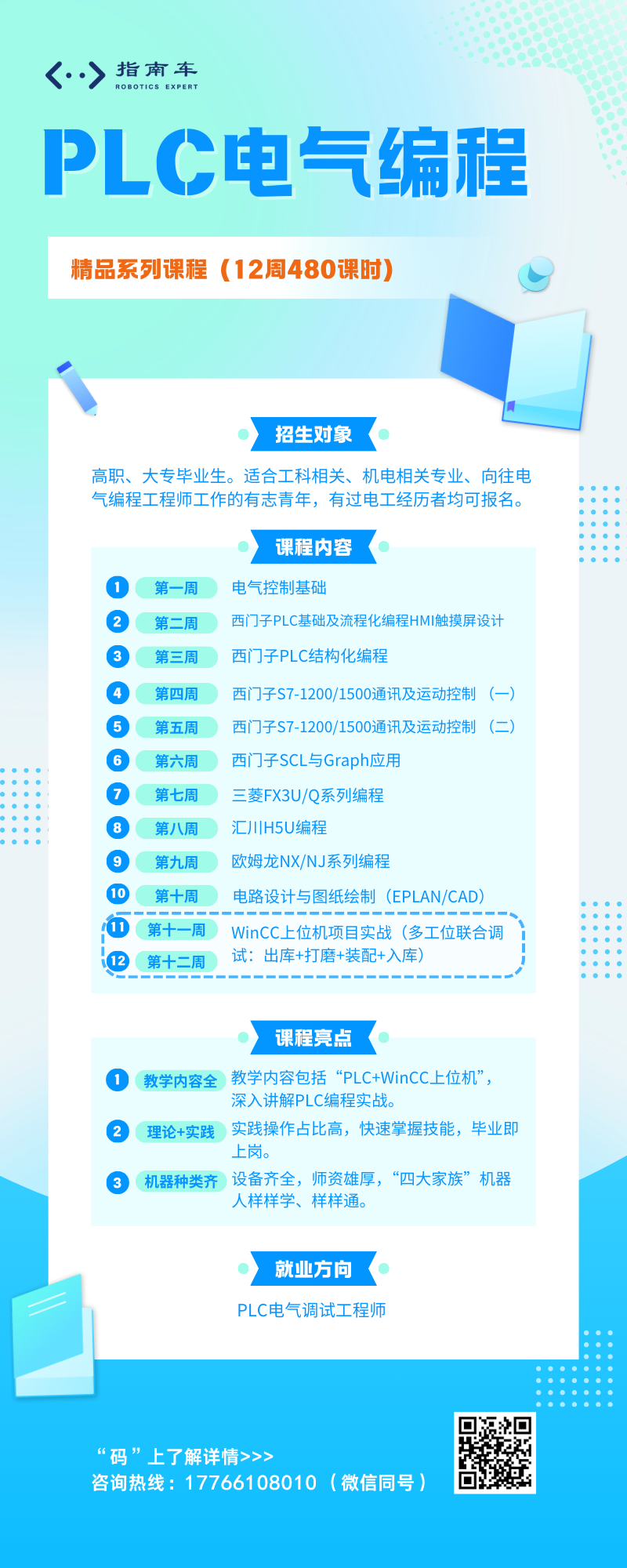
↓ Click “Read Original” to sign up for course inquiries!