PLC networks are composed of several levels of subnetworks, and the communication process between these subnetworks is determined by communication protocols, with the communication method being the core content of the communication protocol. The communication methods include access control methods and data transmission methods. The so-called access control (also known as access control) method refers to how to obtain the right to use the shared communication medium, while the data transmission method refers to how to transmit data after a station has obtained the right to use the communication medium.
1. Cyclic I/O Communication Method
The cyclic I/O communication method is commonly used in remote I/O links of PLCs. The remote I/O link operates in a master-slave manner, with the PLC remote I/O master unit as the master station, and all other remote I/O units as slave stations. A “remote I/O buffer” is established in the master station, using a mailbox structure divided into several sub-boxes corresponding to each slave station—each sub-box is further divided into two sections, one for sending and one for receiving. The communication processor in the master station uses a cyclic scanning method to sequentially exchange data with each slave station, sending data from the sending section of the corresponding sub-box to the slave station and reading data from the slave station into the receiving section of the corresponding sub-box. This cycle continues, allowing the “remote I/O buffer” in the master station to be periodically refreshed.
In the master station, the CPU unit of the PLC is responsible for scanning the user program, processing in a cyclic scanning manner, with a specific time allocated for I/O processing during each cycle, during which it performs read and write operations on local I/O units and the remote I/O buffer. The periodic cyclic scanning of the user program by the PLC CPU unit is asynchronous to the periodic scanning of each remote I/O unit by the PLC communication processor. Although the PLC CPU unit does not directly operate on the remote I/O units, the periodic refresh of the remote I/O buffer means that operations by the PLC CPU unit on the remote I/O buffer are equivalent to directly accessing the remote I/O units. This communication method is simple and convenient but occupies the PLC’s I/O area, making it suitable only for communication involving small amounts of data.
2. Global I/O Communication Method
The global I/O communication method is a serial communication method that shares a storage area, mainly used for communication between PLCs with link areas.
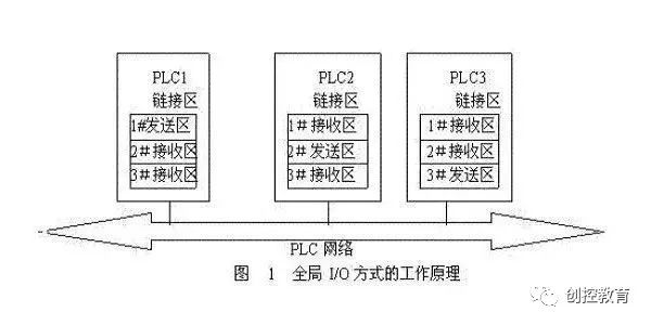
The communication principle of the global I/O method is shown in the above figure. In each PLC’s I/O area in the PLC network, a section is designated as the link area, with each link area adopting a mailbox structure. The sending and receiving areas with the same number are of equal size and occupy the same address range, one being the sending area and the others being receiving areas. Communication is conducted via broadcasting. PLC1 broadcasts the data from the 1# sending area over the PLC network, and PLC2 and PLC3 receive it and store it in their respective 1# receiving areas. PLC2 broadcasts the data from the 2# sending area, and PLC1 and PLC3 receive it and store it in their respective 2# receiving areas. PLC3 broadcasts the data from the 3# sending area, and PLC1 and PLC2 receive it and store it in their respective 3# receiving areas. Clearly, through the above broadcasting communication process, the data in the link areas of PLC1, PLC2, and PLC3 is identical; this process is called the equalization process.
This equalization communication ensures that the data in the link areas of each PLC in the PLC network remains consistent. It contains both the data sent out by itself and the data received from other PLCs. Since each PLC’s link area is the same size and occupies the same address range, accessing its own link area is equivalent to accessing other PLCs’ link areas, thus exchanging data with other PLCs. This makes the link area a true shared storage area, with the shared area serving as an intermediary for data exchange among PLCs.
The link area can be refreshed asynchronously (equalization) or synchronously. Asynchronous refreshing is independent of the user program in the PLC, conducted sequentially by each PLC’s communication processor through broadcast communication, continuously ensuring that all link areas remain equalized; synchronous refreshing is initiated by a send instruction in the user program, refreshing only when the data in the link area’s sending section changes.
In the global I/O communication method, PLCs directly perform read and write operations on the link area, which is simple, convenient, and fast, but it should be noted that a write operation on a certain address in one PLC can only be read from the same address in other PLCs. Like the cyclic I/O method, the global I/O method also occupies the PLC’s I/O area, making it suitable only for communication involving small amounts of data.
3. Master-Slave Bus Communication Method
The master-slave bus communication method, also known as 1:N communication, refers to a bus-structured PLC subnetwork with N stations, where there is only 1 master station and all others are slave stations.
The 1:N communication method employs centralized access control technology to allocate the bus usage rights, typically using a polling table method. A polling table is an ordered list of slave station numbers configured in the master station, which the master station queries in the order of the polling table to see if a slave station wishes to use the bus, thus achieving the allocation of bus usage rights.
For stations with higher real-time requirements, their slave station numbers can appear multiple times in the polling table, granting them higher communication priority. In some 1:N communications, the polling table method is combined with interrupt methods, allowing urgent tasks to interrupt normal cyclic polling to gain priority.
In the 1:N communication method, when a slave station gains the right to use the bus, there are two data transmission methods. One allows only master-slave communication, prohibiting slave-to-slave communication; for data exchange between slave stations, it must be relayed through the master station. The other allows both master-slave communication and slave-to-slave communication, where the slave station can first arrange master-slave communication before scheduling communication with other slave stations.
4. Token Bus Communication Method
The token bus communication method, also known as N:N communication, refers to a bus-structured PLC subnetwork with N stations, where all stations hold equal status, with no distinction between master and slave stations; in other words, all N stations are master stations.
The N:N communication method employs token bus access control technology. A logical ring is formed on the physical bus, allowing a token to circulate in a specific direction. The station that holds the token obtains the right to use the bus. The token bus access control method limits the token holding time for each station, ensuring that each station has the opportunity to gain bus usage rights during one complete cycle of the token, providing priority services, thus ensuring good real-time performance.
The station that obtains the token has two data transmission methods: one is an unacknowledged data transmission method, allowing the station to immediately send data to the destination station, completing the communication process upon sending; the other is an acknowledged data transmission method, where the communication is not considered complete until the destination station receives the token and sends an acknowledgment frame back to the sending station. The latter has a significantly longer response time, reducing real-time performance.
5. Floating Master Communication Method
The floating master communication method, also known as N:M communication, is suitable for bus-structured PLC networks, referring to a bus with M stations, where N (N<m) and="" are="" master="" rest="" slave="" span="" stations="" stations.
The N:M communication method combines token bus and master-slave bus access control technologies. First, the N master stations are formed into a logical ring, with the token circulating in the logical ring to allocate bus usage rights among the N master stations, which is the meaning of floating master.
The master station that obtains the bus usage rights then determines which stations to communicate with during its token holding time based on a polling table configured in the master station, polling other master and slave station numbers in the order of the table.
The master station that obtains the bus usage rights can use various data transmission methods to communicate with the destination station, with the unacknowledged, connectionless method being the fastest.
6. CSMA/CD Communication Method
The CSMA/CD communication method is a random communication method suitable for bus-structured PLC networks, where all stations have equal status, with no distinction between master and slave, using CSMA/CD access control method, i.e., “listen before talk, talk while listen.”
The CSMA/CD access control method cannot guarantee that each station on the PLC network can obtain bus usage rights within a specific time period, making it a non-real-time access control method. However, it adopts a random method, which is simple, and is flexible enough to seize opportunities as long as the bus is free, resulting in a high utilization rate of communication resources. Therefore, in PLC networks, the CSMA/CD communication method is suitable for upper-level production management subnetworks.
The data transmission methods in CSMA/CD communication can include connection-oriented, connectionless, acknowledged, unacknowledged, and broadcast communication, allowing selection based on communication speed and reliability requirements.
The above are the commonly used communication methods in PLC networks. Additionally, a small number of PLC networks utilize other communication methods, such as token ring communication methods, etc.Moreover, in some PLC networks, various communication methods are often integrated and configured at a certain level of the subnet, which is a trend in future technological development.
(Content source from the internet, copyright belongs to the original author)Disclaimer:If there are copyright issues, please contact for deletion!
No individual or organization bears relevant legal responsibilities.
Recommended Reading:
As an engineer, how can you not have this certification?
United in unity, brave in progress, Changkong Education offline student expansion activity in Santai Mountain
Public class video replay | June 28, Siemens DB data block usage methods and precautions
Latest industrial control programming software download (real-time updates)
As an electrician, where do you think your future lies?
Second half of 2019: Empty yourself, let your heart return to zero!