The terminal resistance of the CAN bus is generally 120 ohms. In fact, during the design phase, it consists of two 60 ohm resistors connected in series. There are typically two 120Ω nodes on the bus, which is a basic understanding for anyone who knows a little about CAN bus.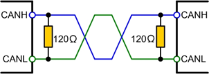 However, as a struggling student, I know this is a commonly used resistance value in various standards, data sheets, and application notes, but what exactly is the specific function of these two terminal resistors? I previously only knew about impedance matching, but what exactly is being matched?So I went on Zhihu and summarized the following knowledge points. Knowing the function of the terminal resistors can help quickly identify issues like unstable waveforms in daily work.
The Function of Terminal Resistors
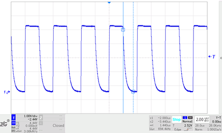
The terminal resistors of the CAN bus serve three purposes:1. Improve anti-interference capability, allowing high-frequency low-energy signals to dissipate quickly.2. Ensure the bus quickly enters a recessive state, allowing the energy of parasitic capacitance to dissipate faster.3. Improve signal quality, placed at both ends of the bus to reduce reflected energy.1. Improve Anti-Interference CapabilityThe CAN bus has two states: ‘dominant’ and ‘recessive’. ‘Dominant’ represents ‘0’, and ‘recessive’ represents ‘1’, determined by the CAN transceiver. The following diagram shows a typical internal structure of a CAN transceiver, with CANH and CANL connected to the bus.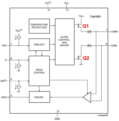 When the bus is dominant, transistors Q1 and Q2 inside the transceiver conduct, creating a voltage difference between CANH and CANL; when recessive, Q1 and Q2 are off, and CANH and CANL are in a passive state with a voltage difference of 0.If there is no load on the bus, the differential resistance value in recessive state is very high, and the internal MOSFETs are in a high-resistance state. External interference only requires a small amount of energy to bring the bus into a dominant state (the minimum voltage threshold for a typical transceiver is only 500mV). If differential mode interference occurs, there will be noticeable fluctuations on the bus, and since there is no place to absorb them, a dominant bit will be created on the bus. To enhance the anti-interference capability of the bus in recessive state, a differential load resistor can be added, with a resistance value as low as possible to eliminate most noise energy’s influence. However, to avoid requiring excessive current for the bus to enter dominant state, the resistance value cannot be too low.2. Ensure Quick Entry into Recessive StateDuring the dominant state, the parasitic capacitance of the bus will be charged, and when returning to recessive state, these capacitors need to discharge. If there are no resistive loads placed between CANH and CANL, the capacitors can only discharge through the internal differential resistance of the transceiver, which is relatively high. According to the characteristics of RC filter circuits, the discharge time will be significantly longer. We conducted a simulation experiment by adding a 220PF capacitor between CANH and CANL of the transceiver, with a bit rate of 500kbit/s. The waveform is shown in the diagram, where the falling edge indicates a prolonged state.
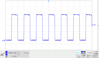
 To ensure the parasitic capacitance of the bus discharges quickly and the bus enters recessive state promptly, a load resistor needs to be placed between CANH and CANL. After adding a 60Ω resistor, the waveform changes as shown in the diagram, indicating that the time taken to transition from dominant to recessive has been reduced to 128nS, comparable to the time taken to establish dominance.
 3. Improve Signal QualityAt higher transition rates, when the signal edge energy encounters impedance mismatch, signal reflections occur; changes in the geometric structure of the transmission cable cross-section will also lead to changes in the characteristic impedance, causing reflections.When energy reflects, the reflected waveform superimposes with the original waveform, causing ringing.At the end of the bus cable, abrupt changes in impedance lead to reflections of signal edge energy, resulting in ringing on the bus signal. If the amplitude of the ringing is too large, it will affect communication quality. By adding a terminal resistor at the end of the cable that matches the cable’s characteristic impedance, this energy can be absorbed, preventing ringing.In a simulation experiment conducted by others (the images are copied from them), with a bit rate of 1Mbit/s, the transceiver CANH and CANL were connected to about 10m of twisted pair cable, and the terminal resistor of 120Ω was used to ensure the recessive transition time, with no load at the end. The end signal waveform is shown in the diagram, where ringing appears at the signal’s rising edge.
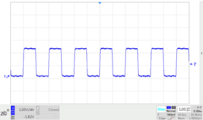
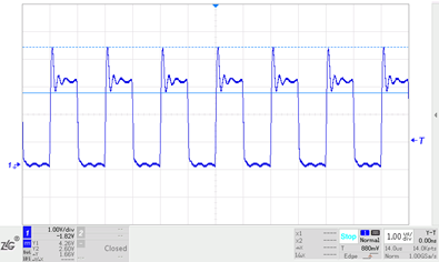 When a 120Ω resistor is added to the end of the twisted pair, the end signal waveform improves significantly, and the ringing disappears.
 In a linear topology, the ends of the cable serve as both the transmitting and receiving ends, so a terminal resistor needs to be added at both ends of the cable.In practical applications, the CAN bus is generally not designed as a perfect bus structure; often it is a hybrid structure of bus and star topologies. In this case, CAN terminal resistors are usually placed at the farthest ends of the harness to closely simulate the standard structure of the CAN bus.
Why Choose 120Ω?
What is impedance? In electrical terms, the resistance to current in a circuit is called impedance. The unit of impedance is ohms, commonly represented as Z, which is a complex number Z = R + i(ωL – 1/(ωC)). Specifically, impedance can be divided into two parts: resistance (real part) and reactance (imaginary part). Reactance includes capacitive reactance and inductive reactance, where the current obstruction caused by capacitance is called capacitive reactance, and the obstruction caused by inductance is called inductive reactance. Here, impedance refers to the modulus of Z.The characteristic impedance of any cable can be determined experimentally. One end of the cable is connected to a square wave generator, and the other end is connected to a variable resistor, with the waveform observed on an oscilloscope. Adjust the resistance value until the signal at the resistor is a well-defined square wave without ringing; this resistance value can be considered consistent with the cable’s characteristic impedance.By using two typical automotive cables twisted into a twisted pair, the characteristic impedance can be determined to be approximately 120Ω, which is also the terminal resistance value recommended by the CAN standard. Therefore, this 120Ω is measured, not calculated, based on the actual characteristics of the harness. Of course, this is also defined in the ISO 11898-2 standard.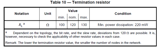
Why Choose 0.25W for Power?
This must also consider some fault states. All interfaces of automotive ECUs need to account for short circuits to power and ground, so we also need to consider the case where the CAN bus node shorts to power.According to standards, short circuits to 18V must be considered. If CANH shorts to 18V, the current will flow through the terminal resistor to CANL, and due to current limiting, the maximum injection current is 50mA (as indicated in the TJA1145 specification).At this point, the power of the 120Ω resistor is 50mA * 50mA * 120Ω = 0.3W.Considering derating at high temperatures, the power rating of the terminal resistor is 0.5W.


 Click to read the original text and apply for free.