The Siemens S7-1200 is a compact, modular PLC that can perform simple logic control, advanced logic control, HMI, and network communication tasks. It is easy to design and implement for automation systems that require network communication capabilities and single or multiple screen HMIs. It has advanced application capabilities that support small motion control systems and process control systems.The SIMATIC S7-1200 features integrated technologies for computation and measurement, closed-loop control, and motion control, making it a highly powerful system capable of handling various types of automation tasks.
The perfect match of the SIMATIC S7-1200 PLC with the new SIMATIC HMI Basic Panel ensures that automation tasks are particularly efficient, easy to develop, and debug.
1. S7-1200 Input and Output Wiring Diagrams
CPU 1211C Wiring Diagram
CPU 1211C AC/DC/Relay (6ES7 211-1BE40-0XB0)
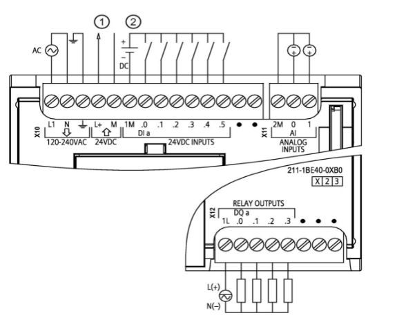
① 24 VDC Sensor Power Supply
② For sinking inputs, connect the load to the “-” terminal (as shown); for sourcing inputs, connect the load to the “+” terminal.
CPU 1211C DC/DC/Relay (6ES7 211-1HE40-0XB0)
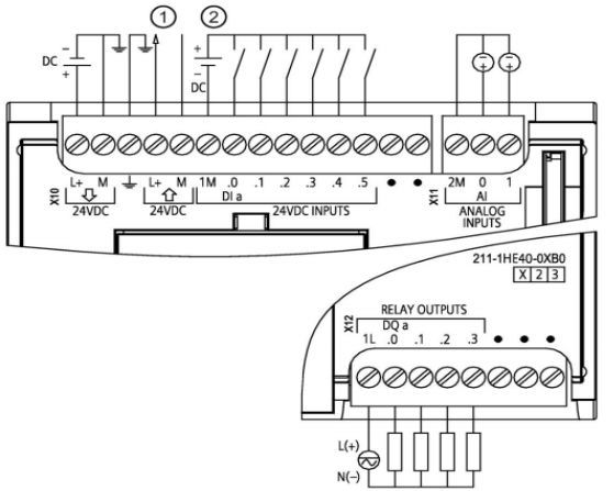
① 24 VDC Sensor Power Supply
② For sinking inputs, connect the load to the “-” terminal (as shown); for sourcing inputs, connect the load to the “+” terminal.
CPU 1211C DC/DC/DC (6ES7 211-1AE40-0XB0)
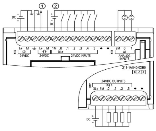
① 24 VDC Sensor Power Supply
② For sinking inputs, connect the load to the “-” terminal (as shown); for sourcing inputs, connect the load to the “+” terminal.
CPU 1212C Wiring Diagram
CPU 1212C AC/DC/Relay (6ES7 212-1BE40-0XB0)
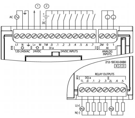
① 24 VDC Sensor Power Supply
② For sinking inputs, connect the load to the “-” terminal (as shown); for sourcing inputs, connect the load to the “+” terminal.
CPU 1212C DC/DC/Relay (6ES7 212-1HE40-0XB0)
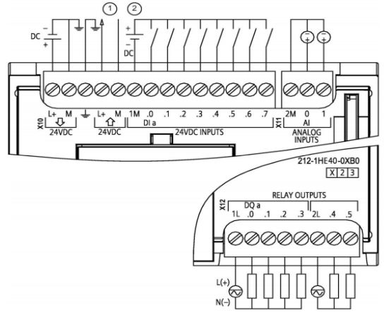
① 24 VDC Sensor Power Supply
② For sinking inputs, connect the load to the “-” terminal (as shown); for sourcing inputs, connect the load to the “+” terminal.
CPU 1212C DC/DC/DC (6ES7 212-1AE40-0XB0)
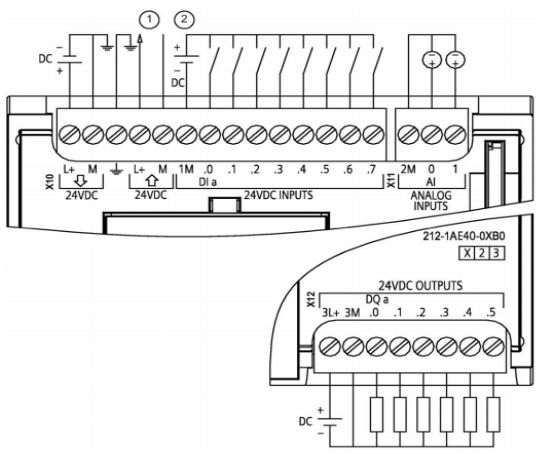
① 24 VDC Sensor Power Supply
② For sinking inputs, connect the load to the “-” terminal (as shown); for sourcing inputs, connect the load to the “+” terminal.
CPU 1214C Wiring Diagram
CPU 1214C AC/DC/Relay (6ES7 214-1BG40-0XB0)
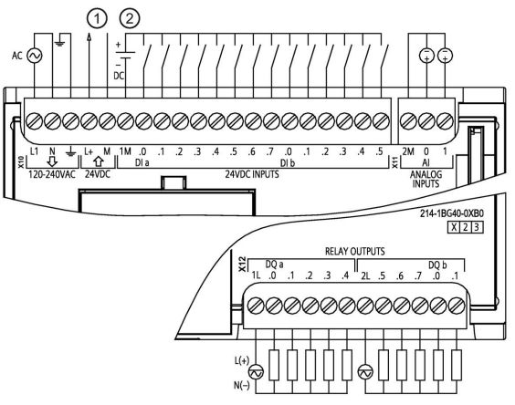
① 24 VDC Sensor Power Supply
② For sinking inputs, connect the load to the “-” terminal (as shown); for sourcing inputs, connect the load to the “+” terminal.
CPU 1214C DC/DC/Relay (6ES7 214-1HG40-0XB0)
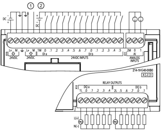
① 24 VDC Sensor Power Supply
② For sinking inputs, connect the load to the “-” terminal (as shown); for sourcing inputs, connect the load to the “+” terminal.
CPU 1214C DC/DC/DC (6ES7 214-1AG40-0XB0)
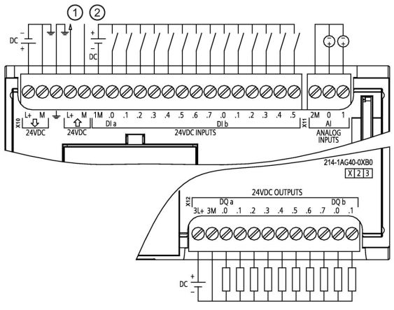
① 24 VDC Sensor Power Supply
② For sinking inputs, connect the load to the “-” terminal (as shown); for sourcing inputs, connect the load to the “+” terminal.
CPU 1215C Wiring Diagram
CPU 1215C AC/DC/Relay (6ES7 215-1BG40-0XB0)
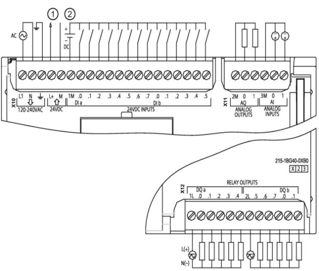
① 24 VDC Sensor Power Supply
② For sinking inputs, connect the load to the “-” terminal (as shown); for sourcing inputs, connect the load to the “+” terminal.
CPU 1215C DC/DC/Relay (6ES7 215-1HG40-0XB0)
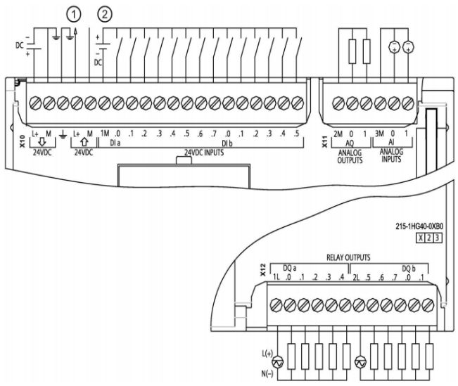
① 24 VDC Sensor Power Supply
② For sinking inputs, connect the load to the “-” terminal (as shown); for sourcing inputs, connect the load to the “+” terminal.
CPU 1215C DC/DC/DC (6ES7 215-1AG40-0XB0)
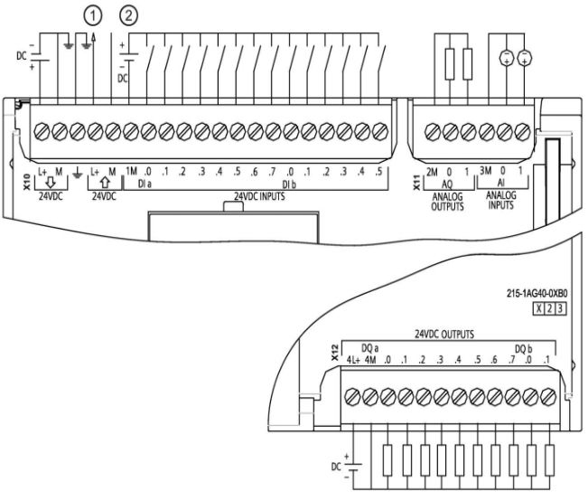
① 24 VDC Sensor Power Supply
② For sinking inputs, connect the load to the “-” terminal (as shown); for sourcing inputs, connect the load to the “+” terminal.
CPU 1217C Wiring Diagram
CPU 1217C DC/DC/DC (6ES7 217-1AG40-0XB0)
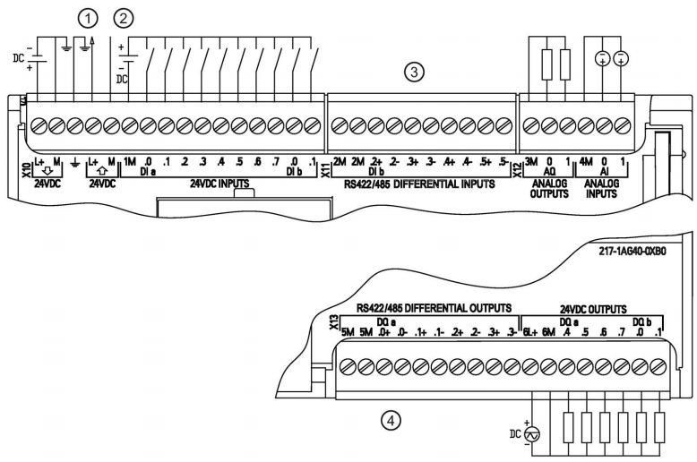
① 24 VDC Sensor Power Supply
② For sinking inputs, connect the load to the “-” terminal (as shown); for sourcing inputs, connect the load to the “+” terminal.
③ 5V Differential Signal Input
④ 5V Differential Signal Output
Common Questions
Can the 5V differential signal of the 1217C be used as a regular DI/DO point?
Answer: No. For details, see the appendix of the “S7-1200 System Manual”.
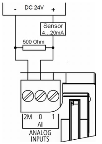
Can the built-in analog input channel of the S7-1200 accept a 0-20mA current signal? How to wire it?
Answer: The built-in analog input channel of the S7-1200 supports a 0-10 V voltage signal. If you need to connect a 0-20mA current signal, you can parallel a 500ohm resistor.
Note: When using a 500Ω resistor, be sure to pay attention to the power consumption of this measurement method. Ensure that when a DC 24 V voltage is applied across the resistor, the power consumption of the resistor is at least 1.16 W. At the same time, the accuracy of this method cannot be guaranteed.
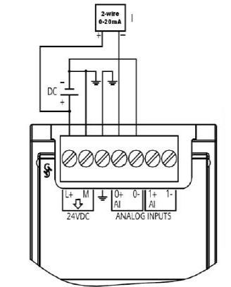
For example, to connect a common two-wire sensor 4-20mA current signal using the built-in analog input channel of the S7-1200, see the diagram below:
2. Digital Signal Module Input and Output Wiring Diagrams
SM 1221 Digital Input
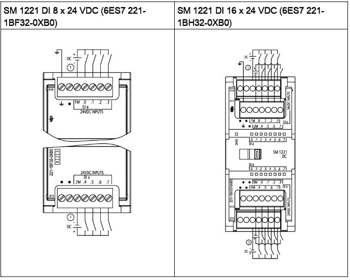
For sinking inputs, connect “-” to “M” (as shown); for sourcing inputs, connect “+” to “M”.
SM 1222 Digital Output
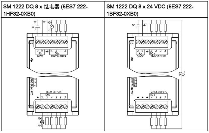
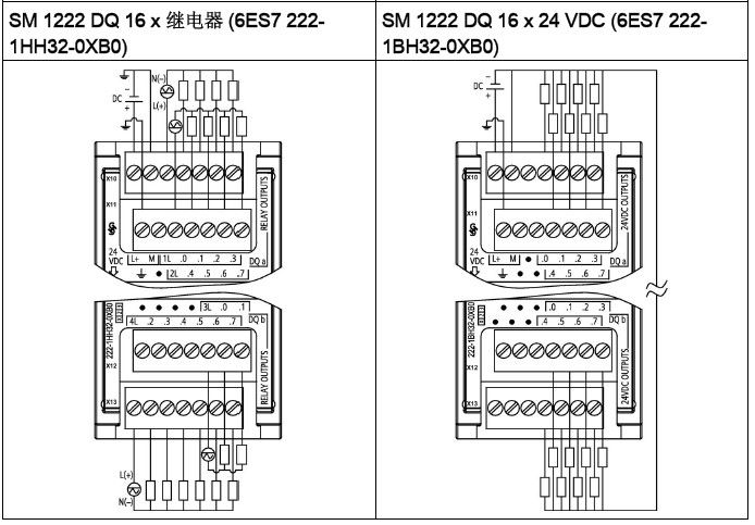
SM1222 DQ 8 Relay Switching Module uses a common terminal to control two circuits: one normally closed contact and one normally open contact.
For example, when output “0” is off, the common terminal (0L) is connected to the normally closed contact (.0X) and disconnected from the normally open contact (.0). When the output point is on, the common terminal (0L) is disconnected from the normally closed contact (.0X) and connected to the normally open contact (.0).
SM 1223 Digital Input/Output
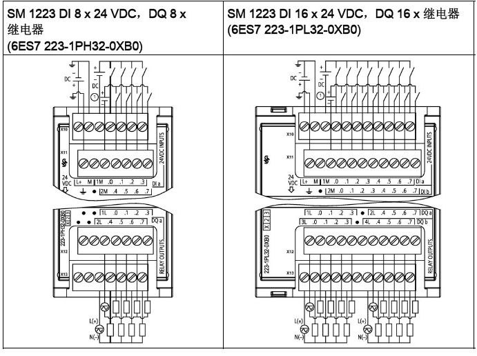
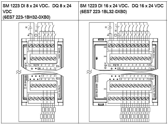
For sinking inputs, connect the load to the “-” terminal (as shown); for sourcing inputs, connect the load to the “+” terminal.
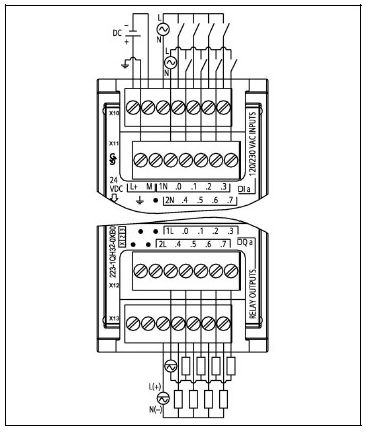
SM 1223 also has AC voltage input and relay output modules, as shown below:
SM 1223 DI 8 x 120/230 VAC, DQ 8 x Relay (6ES7 223-1QH32-0XB0)
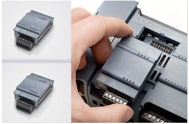
The digital signal board can increase the I/O of the CPU through the signal board (SB, Signal Board). It provides a low-cost and effective expansion for all SIMATIC S7-1200 controllers while maintaining the original space, with SB connected at the front of the CPU.
SB 1221 200KHZ Digital Input Wiring
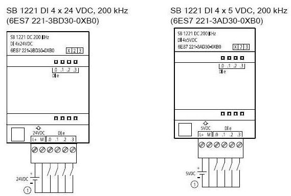
Only supports sourcing input.
SB 1222 200KHZ Digital Output Wiring
For sourcing outputs, connect the load to the “-” terminal (as shown); for sinking outputs, connect the load to the “+” terminal.
SB 1223 200KHZ Digital Input/Output Wiring
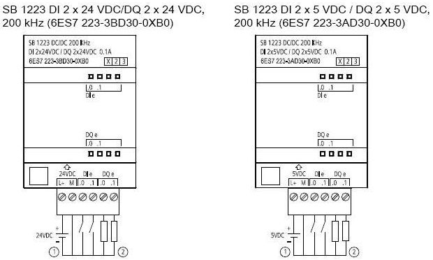
① Only supports sourcing input.
② For sourcing outputs, connect the load to the “-” terminal (as shown); for sinking outputs, connect the load to the “+” terminal.
SB 1223 Digital Input/Output Wiring
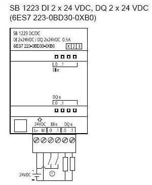
Only supports sinking input.
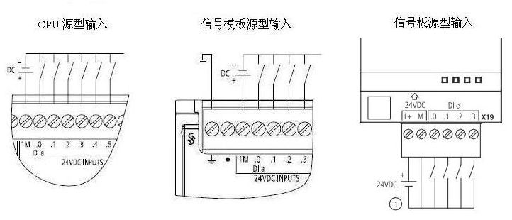
Wiring instructions for sourcing/sinking input support signal boards that support sourcing input:
6ES7 221-3BD30-0XB06ES7 221-3AD30-0XB06ES7 223-3BD30-0XB06ES7 223-3AD30-0XB0 Signal boards that support sinking input:
6ES7 223-0BD30-0XB0 Signal templates that support sourcing input:
6ES7 221-1BF32-0XB06ES7 221-1BH32-0XB06ES7 223-1PH32-0XB06ES7 223-1PL32-0XB06ES7 223-1BH32-0XB06ES7 223-1BL32-0XB0 Signal templates that support sinking input:
6ES7 221-1BF32-0XB06ES7 221-1BH32-0XB06ES7 223-1PH32-0XB06ES7 223-1PL32-0XB06ES7 223-1BH32-0XB06ES7 223-1BL32-0XB0 For reference, see the “S7-1200 System Manual”.
Summary of digital input signal types: All input points of the CPU integrated input and signal templates support both sinking and sourcing input, while the input points of the signal boards support only one type of input, either sourcing or sinking.
Sinking input is shown in the template wiring diagram, sourcing input wiring is referenced in the diagram below.
Wiring instructions for sourcing/sinking output support signal boards that support sourcing output:
6ES7 222-1AD30-0XB06ES7 222-1BD30-0XB06ES7 223-3AD30-0XB06ES7 223-3BD30-0XB06ES7 223-0BD30-0XB0 Note: All transistor output signal modules that support sourcing output only support sourcing output, not sinking output.
Signal boards that support sinking output:
6ES7 222-1AD30-0XB06ES7 222-1BD30-0XB06ES7 223-3AD30-0XB06ES7 223-3BD30-0XB0 Note: For digital output signal types, only the 200 KHZ signal board output supports both sinking and sourcing output, while other signal boards, signal modules, and CPU integrated transistor outputs only support sourcing output.
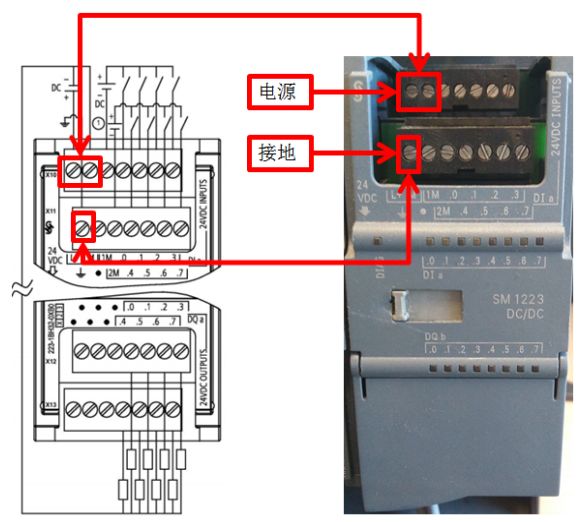
Common QuestionsWhy does the signal output channel indicator light up when SM1223 is connected, but there is no voltage output?
Answer: The output channel indicator light of the S7-1200 expansion module is powered by the bus, but the signal output requires power from the module. The correct wiring method is shown in the diagram below:
3. Analog Module Input and Output Wiring Diagrams
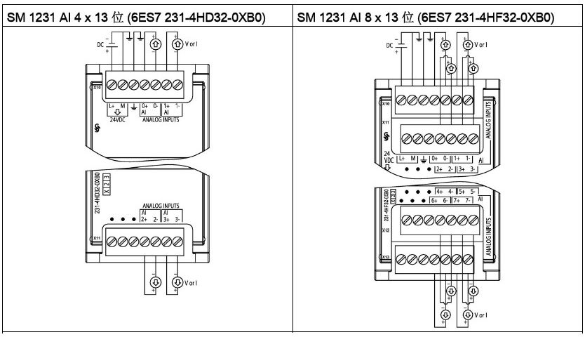
SM1231 Analog Input
SM 1232 Analog Output
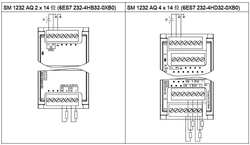
SM 1234 Analog Input/Output
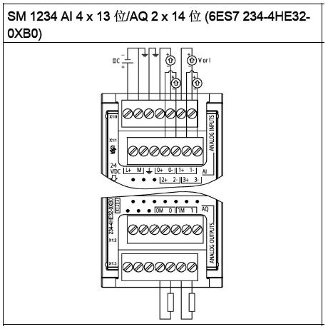
SB 1231 Analog Input (Signal Board)
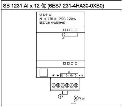
SB 1232 Analog Output (Signal Board)
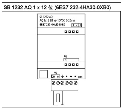
AI Sensor Connection Wiring Method
Figure 1. 4-Wire Sensor
Figure 2. 3-Wire Sensor
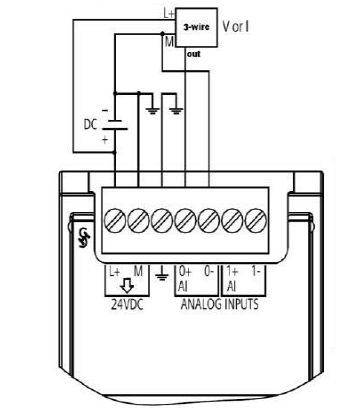
Figure 3. 2-Wire Sensor
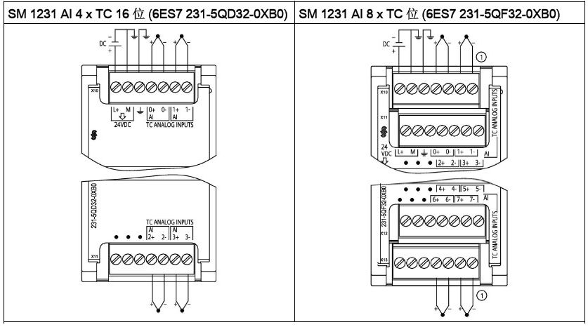
TC Signal Module
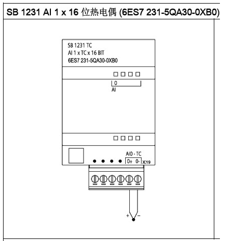
TC Signal Module Wiring
TC Signal Board Wiring
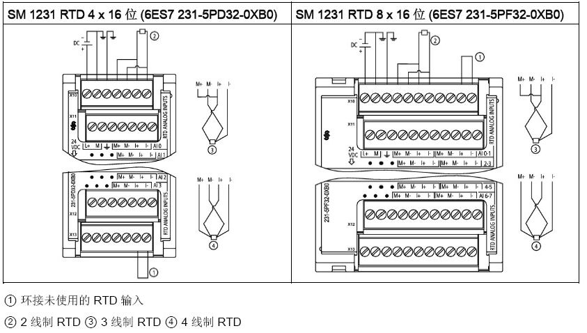
RTD Signal Module
RTD Signal Module Wiring
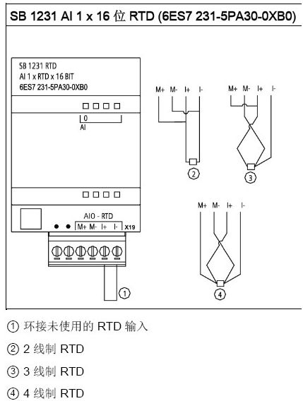
RTD Signal Board Wiring
Recommended Reading
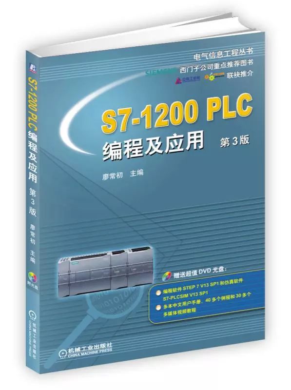
S7-1200 PLC Programming and Application, 3rd Edition
Author: Liao Changchu
ISBN: 9787111563136
Recommended by Siemens Company
Jointly recommended by China Industrial Control Network/China Automation Network
Key book on the new model 1200 PLC from Siemens
The accompanying CD provides programming software STEP 7 V13 SP1 and simulation software S7-PLCSIM V13 SP1, over 20 user manuals, more than 40 examples, and over 30 multimedia video tutorials.

Mechanical Engineering Education (WeChat ID: cmpedu) The WeChat public service account is hosted by the Machinery Industry Press, dedicated to “spreading new knowledge, serving education” and providing free services such as textbook resource downloads, sample book applications, teacher training, publishing topics, and educational information for college teachers.