
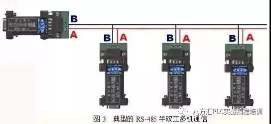
The RS-485 interface forms a half-duplex network, typically using a two-wire system, often employing shielded twisted pair for transmission. This wiring method allows a maximum of 32 nodes to be connected on the same bus topology.Initially, data was output as analog signals for simple process quantities, later instruments used the RS-232 interface, which facilitates point-to-point communication. However, this method does not support networking capabilities, which was addressed by the introduction of RS-485.This article provides a detailed introduction to the RS-485 interface in a Q&A format.

Answer:The RS-232-C interface standard was established earlier and has some shortcomings, mainly four points:
(1) The signal level values of the interface are relatively high, which can damage the interface circuit chips. Furthermore, since it is not compatible with TTL levels, level conversion circuits are necessary to connect with TTL circuits.
(2) The transmission rate is low, with a baud rate of 20Kbps during asynchronous transmission.
(3) The interface uses one signal line and one signal return line to form a common ground transmission method, which is susceptible to common-mode interference, thus having weak noise immunity.
(4) The transmission distance is limited, with a maximum standard transmission distance of 50 feet, practically usable only up to about 50 meters.To address the shortcomings of RS-232-C, new interface standards have emerged, among which RS-485 is one of them, characterized by:
1) The electrical characteristics of RS-485: Logic “1” is represented by a voltage difference of + (2-6)V between the two wires; Logic “0” is represented by a voltage difference of – (2-6)V between the two wires. The signal levels of the interface are lower than those of RS-232-C, making it less likely to damage the interface circuit chips, and this level is compatible with TTL levels, allowing for easy connection with TTL circuits.
2) The maximum data transmission rate of RS-485 is 10Mbps.
3) The RS-485 interface uses a combination of balanced drivers and differential receivers, enhancing common-mode rejection and improving noise immunity.
4) The maximum standard transmission distance for RS-485 is 4000 feet, practically reaching up to 3000 meters. Additionally, the RS-232-C interface allows only one transceiver to be connected on the bus, i.e., single-station capability, while RS-485 allows for up to 128 transceivers to be connected on the bus, i.e., multi-station capability, enabling users to easily establish a device network using a single RS-485 interface.
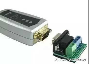
5) Due to the excellent noise immunity, long transmission distance, and multi-station capability of the RS-485 interface, it has become the preferred serial interface. The half-duplex network formed by RS-485 generally requires only two wires, so RS-485 interfaces typically use shielded twisted pairs for transmission. The RS-485 connector uses a DB-9 9-pin plug and socket, with the intelligent terminal RS-485 interface using DB-9 (socket), and the keyboard connection RS-485 interface using DB-9 (pin).
1. Balanced Transmission
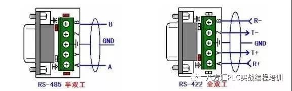
RS-422 and RS-485 differ from RS-232 in that data signals use differential transmission, also known as balanced transmission, utilizing a pair of twisted wires, with one wire defined as A and the other as B.
In general, the positive level between the sending driver A and B is +2 to +6V, representing one logic state, while the negative level is -2 to 6V, representing another logic state. There is also a signal ground C, and in RS-485, there is an “enable” terminal, which is optional in RS-422. The “enable” terminal is used to control the connection and disconnection of the sending driver and transmission line. When the “enable” terminal is active, the sending driver is in a high-impedance state, referred to as the “third state,” distinct from logic “1” and “0.”
The receiver is also defined relative to the sender, with the receiving and sending ends connected through the balanced twisted pairs, where when there is a voltage greater than +200mV between A and B at the receiving end, it outputs a positive logic level, and when less than -200mV, it outputs a negative logic level. The receiver typically receives balanced line voltage levels between 200mV and 6V.
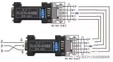
2. Electrical Specifications of RS-422
The full name of the RS-422 standard is “Electrical Characteristics of Balanced Voltage Digital Interface Circuits,” defining the characteristics of the interface circuit. Figure 2 shows a typical RS-422 four-wire interface. In reality, there is also a signal ground wire, making a total of five wires. Figure 1 defines the pin configuration of its DB9 connector. Due to the high input impedance of the receiver and the stronger driving capability of the sending driver compared to RS-232, it allows for multiple receiving nodes to be connected on the same transmission line, with a maximum of 10 nodes. This means one master device and the rest as slave devices; however, slave devices cannot communicate with each other, thus RS-422 supports point-to-multipoint bi-directional communication. The receiver input impedance is 4k, so the maximum load capability of the sender is 10×4k + 100Ω (termination resistance). The RS-422 four-wire interface does not require controlling data direction since it uses separate sending and receiving channels, allowing any necessary signal exchange between devices to be implemented either by software (XON/XOFF handshaking) or hardware (with a pair of separate twisted pairs). The maximum transmission distance of RS-422 is 4000 feet (approximately 1219 meters), and the maximum transmission rate is 10Mb/s. The length of the balanced twisted pair inversely relates to the transmission rate; only below 100kb/s can the maximum transmission distance be achieved. The highest transmission rate can only be obtained over very short distances. Generally, the maximum transmission rate on a 100-meter twisted pair is only 1Mb/s.
RS-422 requires a termination resistor, which should have a resistance approximately equal to the characteristic impedance of the transmission cable. In short-distance transmission, termination resistors may not be required, generally below 300 meters. The termination resistor is connected at the farthest end of the transmission cable.
3. Electrical Specifications of RS-485
Since RS-485 is developed based on RS-422, many of its electrical specifications are similar to those of RS-422. Both use balanced transmission and require termination resistors on the transmission line, etc. RS-485 can use two-wire and four-wire configurations; the two-wire system can achieve true multi-point bi-directional communication.
In contrast, using a four-wire connection, similar to RS-422, can only achieve point-to-multipoint communication, meaning there can only be one master device and the rest as slave devices, but RS-485 has improvements, allowing a maximum of 32 devices to be connected on the bus, regardless of whether it is a four-wire or two-wire configuration.
Another difference between RS-485 and RS-422 is that their common-mode output voltages differ; RS-485 ranges from -7V to +12V, while RS-422 ranges from -7V to +7V. The minimum input impedance of RS-485 receivers is 12k, while RS-422 is 4k. RS-485 meets all RS-422 specifications, allowing RS-485 drivers to be used in RS-422 networks.
Like RS-422, RS-485 has a maximum transmission distance of approximately 1219 meters and a maximum transmission rate of 10Mb/s. The length of the balanced twisted pair inversely relates to the transmission rate; only below 100kb/s can the maximum cable length be used. The highest transmission rate can only be obtained over very short distances. Generally, the maximum transmission rate on a 100-meter twisted pair is only 1Mb/s.
RS-485 requires two termination resistors, which should have a resistance equal to the characteristic impedance of the transmission cable. In short-distance transmission, termination resistors may not be required, generally below 300 meters. Termination resistors are connected at both ends of the transmission bus.
RS-422 supports up to 10 nodes, while RS-485 supports 32 nodes, forming a multi-node network. The network topology typically adopts a terminal-matched bus structure and does not support ring or star networks. When constructing a network, the following points should be noted:
1. Use a twisted pair cable as the bus to connect each node in series. The lead length from the bus to each node should be as short as possible to minimize the impact of reflected signals in the leads on the bus signal. The image shows some common incorrect connection methods (a, c, e) and correct connection methods (b, d, f) in practical applications. Although the three incorrect network connections (a, c, e) may work normally at short distances and low speeds, their adverse effects will become increasingly severe as communication distance increases or communication speed rises, mainly due to signal reflections at the ends of each branch superimposing on the original signal, resulting in signal quality degradation.
2. Pay attention to the continuity of the bus’s characteristic impedance; signal reflections will occur at points of impedance discontinuity. The following situations are likely to produce such discontinuities: different cables used in different sections of the bus, too many transceivers installed closely together on a certain section of the bus, or excessively long branch lines extending to the bus.
In summary, a single, continuous signal channel should be provided as the bus.
For RS-422 and RS-485 bus networks, termination resistors are generally required for matching. However, under short distances and low speeds, termination matching may not need to be considered. So, under what circumstances is matching unnecessary? Theoretically, when sampling at the midpoint of each receiving data signal, as long as the reflected signal attenuates to a sufficiently low level before sampling begins, matching can be disregarded. However, this is difficult to grasp in practice. An article from MAXIM in the US mentions an empirical principle that can be used to determine under what data rates and cable lengths matching is necessary: When the signal transition time (rise or fall time) exceeds three times the time required for the electrical signal to travel unidirectionally along the bus. For example, the RS-485 interface MAX483, which has a limited slope characteristic, has a minimum rise or fall time of 250ns, and the typical signal transmission rate on twisted pairs is approximately 0.2m/ns (for 24AWG PVC cable), so as long as the data rate is within 250kb/s and the cable length does not exceed 16 meters, using MAX483 as the RS-485 interface, termination matching can be omitted.
Generally, termination matching uses termination resistors, as previously mentioned, where RS-422 connects the termination resistor at the far end of the bus cable, while RS-485 should connect termination resistors at both the start and end of the bus cable. The termination resistor is generally 100Ω in RS-422 networks and 120Ω in RS-485 networks. This is equivalent to the resistance of the cable’s characteristic impedance, as most twisted pair cables have a characteristic impedance of about 100 to 120Ω. This matching method is simple and effective, but it has a drawback: the matching resistors consume considerable power, making it less suitable for systems with strict power consumption limits.
Another, more power-efficient matching method is RC matching, which uses a capacitor C to block DC components, saving a significant amount of power. However, the selection of capacitor C value is challenging, requiring a compromise between power consumption and matching quality.
Another method involves using diodes for matching; although this scheme does not achieve true “matching,” it utilizes the clamping effect of diodes to quickly attenuate reflected signals, improving signal quality. The energy-saving effect is significant.
Grounding in electronic systems is crucial but often overlooked. Improper grounding can lead to unstable operation of electronic systems and even jeopardize system safety. Grounding for RS-422 and RS-485 transmission networks is equally important, as an unreasonable grounding system can affect the stability of the entire network, especially in harsh working environments and over long transmission distances, where grounding requirements are more stringent. Otherwise, the interface failure rate will be high. In many cases, connecting RS-422 and RS-485 communication links is simply done by connecting the “A” and “B” ends of each interface with a twisted pair. However, neglecting the connection of signal ground often works normally in many situations but poses significant risks for two reasons:
1. Common-Mode Interference Issues: As previously mentioned, both RS-422 and RS-485 interfaces use differential signal transmission and do not require detection relative to a reference point; the system only needs to detect the potential difference between the two wires. However, people often overlook that transceivers have a certain common-mode voltage range, with RS-422’s common-mode voltage range being -7 to +7V and RS-485’s common-mode voltage range being -7 to +12V. Only by meeting these conditions can the entire network operate normally. When the common-mode voltage in the network line exceeds this range, it will affect the stability and reliability of communication, potentially damaging the interface. For example, when sending driver A sends data to receiver B, the output common-mode voltage of sending driver A is VOS. Due to the independent grounding systems of the two systems, there is a ground potential difference VGPD. Thus, the common-mode voltage at the receiver input can be calculated as VCM=VOS+VGPD. Both RS-422 and RS-485 standards stipulate that VOS≤3V, but VGPD can vary greatly (dozens of volts), potentially accompanied by strong interference signals, causing the receiver’s common-mode input VCM to exceed normal limits, generating interference currents on the transmission line that can disrupt normal communication or even damage communication interface circuits.
2. EMI Issues: The common-mode portion of the output signal from the sending driver needs a return path; without a low-resistance return channel (signal ground), it will return to the source in a radiated form, making the entire bus act like a large antenna radiating electromagnetic waves.
For the above reasons, despite using differential balanced transmission, both RS-422 and RS-485 networks must have a low-resistance signal ground. A low-resistance signal ground connects the working grounds of the two interfaces, shorting the common-mode interference voltage VGPD.
This signal ground can be an additional wire (non-shielded twisted pair) or the shield layer of a shielded twisted pair. This is the most common grounding method.
It is important to note that this approach is only effective against high-impedance common-mode interference; since the interference source has a high impedance, shorting it will not generate significant ground loop current, having little impact on communication. When the common-mode interference source has low impedance, a large loop current will form on the ground line, affecting normal communication. The author believes that the following three measures can be taken:
(1) If the interference source impedance is not very low, a current limiting resistor can be added to the ground line to limit the interference current. Increasing the grounding resistance may raise the common-mode voltage, but as long as it remains within an appropriate range, it will not affect normal communication.
(2) Use floating ground technology to isolate the grounding loop. This is a commonly used and very effective method; when the common-mode interference impedance is very low, the above method may not work. In this case, consider isolating the nodes that introduce interference (e.g., field devices in harsh working environments) by floating them (i.e., isolating the circuit ground from the chassis or ground), thus breaking the grounding loop and preventing significant loop current.
(3) Use isolation interfaces. In some situations, for safety or other reasons, circuit grounds must be connected to the chassis or ground and cannot be floated; isolation interfaces can be used to break the grounding loop, but there should still be a ground wire connecting the common terminal on the isolated side with the working ground of other interfaces.
Both RS-422 and RS-485 standards specify a receiver threshold of ±200mV. This specification provides relatively high noise suppression capability; as mentioned earlier, when the level of receiver A is more than +200mV higher than that of B, the output is positive logic; conversely, it outputs negative logic. However, due to the existence of the third state, after the host sends a piece of information data, it places the bus in the third state, meaning that when the bus is idle, there is no signal driving the bus, causing the voltage between A and B to drop to between -200mV and +200mV, eventually approaching 0V, leading to a problem: The output state of the receiver becomes uncertain. If the output of the receiver is 0V, the slave device in the network interprets it as a new start bit and attempts to read subsequent bytes; since there will never be a stop bit, it results in a frame error, and no device requests the bus, causing the network to become paralyzed. Besides the idle condition causing the voltage difference between the two wires to fall below 200mV, open or short circuits can also lead to this condition. Therefore, measures should be taken to avoid the receiver being in an uncertain state.
Typically, a bias is added to the bus; when the bus is idle or open, bias resistors are used to keep the bus in a defined state (differential voltage ≥ -200mV). As shown in Figure 1. Pulling A to ground and B to 5V, with typical resistor values around 1kΩ, the exact values vary with cable capacitance.
The above method is a classic approach, but it still cannot solve the problem of bus short circuits. Some manufacturers shift the receiver threshold to -200mV/-50mV to resolve this issue.
As previously mentioned, the signal grounding measures only protect against low-frequency common-mode interference and are ineffective against high-frequency transient interference. Since transmission lines act as inductors for high-frequency signals, the ground line effectively becomes an open circuit for high-frequency transient interference. Although such transient interference lasts for a short time, it can have hundreds or thousands of volts.
In practical application environments, there is always a possibility of high-frequency transient interference. Generally, switching large inductive loads such as motors, transformers, relays, etc., or during lightning can generate very high levels of transient interference, which, if not properly protected, can damage RS-422 or RS-485 communication interfaces. To protect against such transient interference, isolation or bypass methods can be employed.
1. Isolation Protection Method: This scheme effectively transfers transient high voltage to the electrical isolation layer in the isolation interface; due to the high insulation resistance of the isolation layer, it does not produce damaging surge currents, thus protecting the interface. Typically, high-frequency transformers, optocouplers, and other components are used to achieve electrical isolation, and some device manufacturers integrate all these components into a single IC for convenient use. The advantage of this scheme is its ability to withstand high voltage and prolonged transient interference, making it relatively easy to implement, but it comes at a higher cost.
2. Bypass Protection Method: This method uses transient suppression components (such as TVS, MOV, gas discharge tubes, etc.) to bypass harmful transient energy to ground. The advantage is lower cost, but the downside is limited protection capability, only protecting against transient interference within a certain energy range, and the duration cannot be long, and it requires a good ground connection for effective implementation. In practical applications, these two methods are often combined flexibly, as shown in Figure 1. In this method, the isolation interface isolates large transient interference, while bypass components protect the isolation interface from being breakdown by excessive transient voltages.
There can only be one transmitter sending on the RS-485 bus at any time. In half-duplex mode, only one master can send at a time. In full-duplex mode, the master can always send, while the slave can send only one at a time.
In long line signal transmission, termination matching resistors are generally required at the receiving end to avoid signal reflection and echoes. The value of the termination matching resistor depends on the impedance characteristics of the cable and is independent of the cable length.
RS-485/RS-422 generally uses twisted pairs (shielded or unshielded) for connections, with termination resistors typically ranging from 100 to 140Ω, with a typical value of 120Ω. In practical configurations, one termination resistor is connected at each terminal node of the cable, i.e., at the nearest and farthest ends, while nodes in the middle section should not connect termination resistors, as this would lead to communication errors.
Because RS-485/RS-422 requires that after sending data is complete, all sending enable control signals must be turned off, while keeping the receiving enable active; at this point, the bus driver enters a high-impedance state, and the receiver can monitor whether there is new communication data on the bus. However, during this time, the bus is in a passive driving state (if there are termination resistors, the differential level between A and B is 0, leading to uncertain receiver output, and the receiver is very sensitive to changes in the differential signal on lines A and B; if there are no termination resistors, the bus is in a high-impedance state, resulting in uncertain receiver output), making it susceptible to external noise interference. When the noise voltage exceeds the input signal threshold (typically ±200mV), the receiver will output data, causing the corresponding UART to receive invalid data, leading to errors in subsequent normal communications; another situation may occur during the moment of turning the sending enable control on/off, causing the receiver to output signals, which will also lead to UART receiving errors.
Solutions:
1) Use pull-ups on the non-inverting input of the bus (line A) and pull-downs on the inverting input (line B) to clamp the bus, ensuring the receiver output remains at a fixed “1” level;
2) Replace the interface circuit with MAX308x series products that have built-in fault-tolerant modes;
3) Eliminate errors through software by adding 2-5 start synchronization bytes in the communication data packet, ensuring that actual data communication only begins after meeting the synchronization header.
1. Signal Reflections in Communication Cables
During communication, signal reflections can occur for two reasons: Impedance discontinuity and impedance mismatch. Impedance discontinuity occurs when the signal encounters a significantly lower or zero cable impedance at the end of the transmission line, causing reflections, similar to light reflecting when transitioning between different media. To eliminate this reflection, a termination resistor equal to the cable’s characteristic impedance must be connected at the end of the cable to ensure impedance continuity. Since signals travel bidirectionally on the transmission cable, a similar termination resistor can also be connected at the other end; theoretically, if a termination resistor equal to the cable’s characteristic impedance is connected at the end of the transmission cable, signal reflections should no longer occur. However, in practical applications, due to the characteristics of the transmission cable and communication baud rate, the characteristic impedance may not perfectly match the termination resistor, so some degree of signal reflection will still exist.
Another cause of signal reflection is the mismatch between the data transceiver and the transmission cable. This type of reflection mainly manifests when the communication line is idle, leading to data confusion across the network.
Ultimately, signal reflections affect data transmission because they trigger the receiver’s input comparator, causing the receiver to receive incorrect signals, resulting in CRC errors or entire data frame errors.
In signal analysis, the parameter used to measure the strength of the reflected signal is RAF (Reflection Attenuation Factor). Its calculation formula is as follows:
RAF=20lg(Vref/Vinc) (1)
Where:Vref is the voltage of the reflected signal; Vinc is the voltage of the incident signal at the connection point between the cable and the transceiver or termination resistor.
Specific measurement methods are shown in Figure 3. For example, if the peak-to-peak value of the incident sine wave signal at 2.5MHz is +5V, and the reflected signal’s peak-to-peak value is +0.297V, then the reflection attenuation factor for this communication cable at a 2.5MHz communication rate is: RAF=20lg(0.297/2.5)=-24.52dB
To mitigate the impact of reflected signals on communication lines, noise suppression and bias resistors are typically employed. In practical applications, for relatively small reflected signals, the bias resistor method is often used for simplicity and convenience. The principle of improving communication reliability through bias resistors in communication lines will be detailed later.
The second factor affecting signal transmission is signal attenuation during transmission through the cable. A transmission cable can be viewed as an equivalent circuit composed of distributed capacitance, distributed inductance, and resistance.
The distributed capacitance C of the cable is mainly generated by the two parallel conductors of the twisted pair. The resistance of the conductors has a negligible effect on the signal and can be ignored. Signal loss mainly results from the LC low-pass filter formed by the cable’s distributed capacitance and inductance. The LAN standard-type two-core inductance used in PROFIBUS (the standard cable selected by Siemens for DP bus) has different attenuation coefficients at various baud rates.
The third factor affecting communication performance is the magnitude of the pure resistive load (also known as DC load). Here, the pure resistive load mainly consists of termination resistors, bias resistors, and RS-485 transceivers.
In describing the RS-485 specification, it was mentioned that RS-485 drivers can support 32 nodes with a configuration of a 150Ω termination resistor, while still being able to output at least 1.5V of differential voltage. The input resistance of a receiver is 12kΩ, and the equivalent circuit of the entire network is shown in Figure 5. Based on this calculation, the load capacity of the RS-485 driver is: RL=32 input resistances in parallel || 2 termination resistors = ((12000/32)×(150/2))/((12000/32)+(150/2))≈51.7Ω
Currently, commonly used RS-485 drivers include MAX485, DS3695, MAX1488/1489, and SN75176A/D used by Huili Company, some of which can achieve load capacities of up to 20Ω. Without considering many other factors, the maximum number of nodes that a driver can support will far exceed 32.
When the communication baud rate is relatively high, it is essential to have bias resistors on the line. The connection method for bias resistors. Their function is to pull the level on the bus away from 0V when there is no data (idle state). This way, even if small reflected signals or noise occur in the line, the data receivers connected to the bus will not produce erroneous actions due to these signals. The following example illustrates how to calculate the size of the bias resistor: Termination resistor Rt1=Rr2=120Ω;
Assuming the maximum peak-to-peak value of reflected signals Vref≤0.3Vp-p, then the negative half-cycle voltage Vref≤0.15V; the reflected current caused by the termination resistor due to the reflected signal Iref≤0.15/(120||120)=2.5mA. The typical hysteresis voltage value of RS-485 transceivers (including SN75176) is 50mV, thus:
(Ibias-Iref)×(Rt1||Rt2)≥50mV
Therefore, the bias current from the bias resistor needs to be Ibias≥3.33mA
+5V=Ibias(Rup+Rdown+(Rt1||Rt2)) (2)
Through equation (2), it can be calculated that Rup=Rdown=720Ω
In practical applications, there are two methods for adding bias resistors to the RS-485 bus:
(1) Distributing the bias resistors equally to each transceiver on the bus. This method adds bias resistors to each transceiver connected to the RS-485 bus, providing each transceiver with a bias voltage.
(2) Using a pair of bias resistors on a section of the bus. This method is effective against large reflected signals or interference on the bus. It is worth noting that the addition of bias resistors increases the load on the bus.
When designing the configuration of a network composed of RS-485 buses (bus length and number of loads), three parameters should be considered: pure resistive load, signal attenuation, and noise margin. The pure resistive load and signal attenuation have been discussed earlier; now we will discuss noise margin (Noise Margin). The noise margin of RS-485 bus receivers should be at least greater than 200mV. The previous discussion assumed a noise margin of 0.
In practical applications, to enhance the bus’s anti-interference capability, it is generally hoped that the system’s noise margin is somewhat better than what is specified in the EIARS-485 standard. The following formula shows the relationship between the number of loads on the bus and the length of the communication cable: Vend=0.8(Vdriver-Vloss-Vnoise-Vbias) (3)
Where: Vend is the signal voltage at the end of the bus, which is specified as 0.2V during standard measurement; Vdriver is the output voltage of the driver (dependent on the number of loads). If the number of loads is between 5 and 35, Vdriver=2.4V; If the number of loads is less than 5, Vdriver=2.5V; If the number of loads is greater than 35, Vdriver≤2.3V); Vloss is the loss of the signal during transmission through the bus (related to the specifications and length of the communication cable), as provided by the standard cable attenuation coefficient; using the formula attenuation coefficient b=20lg(Vout/Vin), it can be calculated that Vloss=Vin-Vout=0.6V (Note: the communication baud rate is 9.6kbps, and the cable length is 1km; if the baud rate increases, Vloss will also increase); Vnoise is the noise margin, which is specified as 0.1V during standard measurement; Vbias is the bias voltage provided by bias resistors (typical value is 0.4V).
The multiplication by 0.8 in equation (3) is to prevent the communication cable from entering a fully loaded state. From equation (3), it can be seen that the size of Vdriver is inversely related to the number of loads on the bus, and the size of Vloss is inversely related to the length of the bus; the other parameters depend only on the type of driver used.
Therefore, once the RS-485 driver has been selected, the maximum number of loads that can be supported is directly related to the maximum distance the signal can be transmitted at a fixed communication baud rate. The specific relationship is:
Within the allowable range of the bus, the more loads there are, the shorter the distance the signal can be transmitted; the fewer loads there are, the farther the signal can be transmitted.
The distributed capacitance of the cable is mainly generated by the two parallel conductors of the twisted pair. Additionally, there is also distributed capacitance between the conductors and ground, though it is small, it cannot be ignored in analysis. The impact of distributed capacitance on bus transmission performance mainly arises because the transmission on the bus involves baseband signals, which can only be expressed as “1” and “0.” In special bytes, such as 0x01, the “0” signal allows sufficient charging time for the distributed capacitance, while when the “1” signal arrives, the charge in the distributed capacitance does not have enough time to discharge, resulting in (Vin+) – (Vin-) > 200mV, causing the receiver to misinterpret it as “0,” ultimately leading to CRC check errors and errors in the entire data frame transmission.
Due to the influence of distributed capacitance on the bus, data transmission errors occur, thus degrading the performance of the entire network. There are two ways to solve this issue:
(1) Reduce the data transmission baud rate;
(2) Use cables with low distributed capacitance to improve the quality of the transmission line.
1. If at any time during the communication process, information can only be transmitted from one party A to another party B, it is called simplex.
2. If at any time, information can be transmitted from A to B and also from B to A, but only one direction of transmission exists, it is called half-duplex transmission.
3. If at any time, there exists bidirectional signal transmission from A to B and B to A on the line, it is called full-duplex.
Telephone lines are two-wire full-duplex channels.
Due to the use of echo cancellation technology, the bidirectional transmission signals do not cause confusion.
Full-duplex channels sometimes separate the receiving and transmitting channels, using separate lines or frequency bands to transmit signals in opposite directions, such as in loopback transmission.
Free materials available, hurry to message the editor on the homepage!

To: The ever-growing Bafanghui community
As engineers, if your monthly salary is below 8000, you should click in
《Large PLC Programming Wisdom – Nuclear Explosion Class》: Very 6+1 Brand Upgrade Plan
Learning VS Observing: When others are already earning over 10,000 a month, buying houses and cars, are you still hesitating?

Reply with “Name + Phone” to grab a seat, limited quantity, take action!!!

BFH
Training Courses:
Practical Mitsubishi PLC Programming, Practical Weichuang Touch Screen Programming, Practical Encoder High-Speed Counter Course, Practical Frequency Converter Programming Application, Practical Stepper Motor Programming Application, Practical Servo Motor Programming Application, PLC Touch Screen Decryption Course, etc. The course content includes a complete set of processes undertaken by engineers, as well as technical support provided to students after they step into engineering positions. In special circumstances, the instructor may provide on-site service.
Free Course Offers:
Electromagnetic Valve Application Course,
Electrical CAD Drawing Course,
Control Box Wiring Wisdom,
Electrician Remedial Course,
Computer Quick Application Course,
Electrical Engineer Interview Course,
Electrical Engineer Career Wisdom,
Personal Tutoring Course for Electrical Engineers
Free Course Offers:
Electrical Automation Selection Course,
Automation Programming Salon (updated weekly),
Automation Project Development,
Proficient Learning of Stepper Motors, Servo Motors
and other motion control. Dozens of real devices
for hands-on practice help students quickly become engineers; learning skills should not only be theoretical,
but should combine practice with theory, with the goal of making students engineers.