Control Requirements
Three switches are used to operate the PLC to control the frequency converter driving the electric motor for delayed forward and reverse operation. One switch is used for forward control, one switch is used for stop control, and one switch is used for reverse control. When the forward switch is closed, the motor runs forward for a delay of 20s, with a running frequency of 30Hz (corresponding to a motor speed of 1680r/min); when the stop switch is closed, the motor stops; when the reverse switch is closed, the motor runs in reverse for a delay of 15s, with a running frequency of 30Hz (corresponding to a motor speed of 1680r/min).
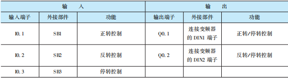
PLC Input and Output Terminal Allocation
The PLC uses the Siemens S7-200 series CPU221 DC/DC/DC, and the allocation of its input and output terminals is shown in Table 10-1.
Table 10-1 PLC Input and Output (I/O) Terminal Allocation
Circuit Wiring
Using 3 switches to operate the PLC to control the frequency converter driving the electric motor for delayed forward and reverse operation as shown in Figure 10-1.
Frequency Converter Parameter Settings
During parameter settings, it is generally recommended to reset all parameters of the frequency converter to factory default values first, then set the motor parameters, and finally set other parameters.
1) Reset all parameters of the frequency converter to factory default values. On the BOP or AOP, first set the debugging parameter filter parameter P0010 = 3, then set the factory reset parameter P0970 = 1, and then press the P key, to start the parameter reset, which takes about 3 minutes to complete the reset process, resetting the parameters of the frequency converter to factory default values.
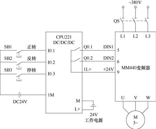
Figure 10-1 PLC Control Circuit for Delayed Forward and Reverse Operation of Electric Motor
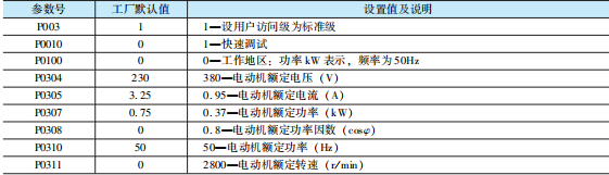
2) Set the motor parameters. When setting the motor parameters, set P0100 = 1 to enter quick parameter debugging, and set some main parameters of the motor according to the motor nameplate (see Table 10-2), after completing the motor parameter settings, set P0100 = 0 to let the frequency converter exit quick debugging, entering the ready-to-run state.
Table 10-2 Motor Parameter Settings
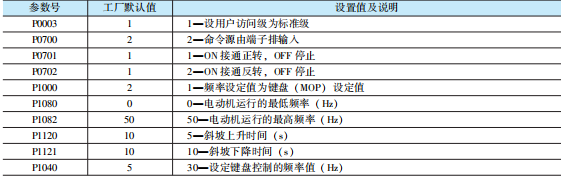
3) Other parameter settings. Other parameters are mainly used to set the functions of digital input terminals, speed control methods, and frequency ranges of motor speeds, etc., see Table 10-3 for details.
Table 10-3 Other Parameter Settings
PLC Control Program and Explanation
Using three switches to operate the PLC to control the frequency converter driving the electric motor for delayed forward and reverse operation, the PLC program and explanation are shown in Figure 10-2.
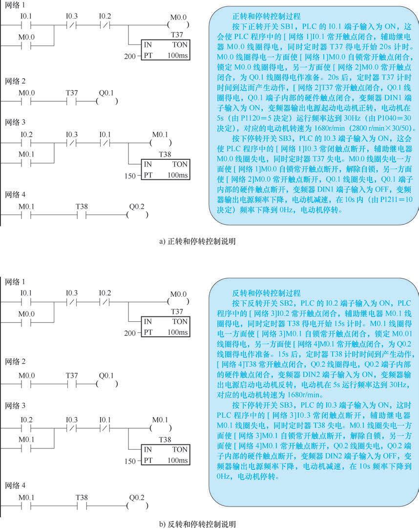
Figure 10-2 Using Three Switches to Operate the PLC to Control the Frequency Converter Driving the Electric Motor for Delayed Forward and Reverse Operation PLC Program and Explanation
 Scan to add WeChat for more learning materials