Example 1: It was functioning normally the day before, but suddenly both manual and remote controls stopped working the next day.
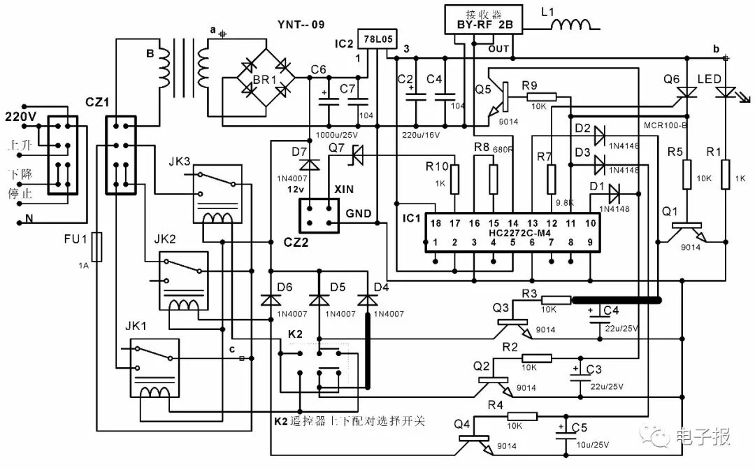
Analysis and Repair: Based on the fault phenomenon analysis, a power circuit anomaly was suspected. To facilitate repairs, a circuit diagram was drawn based on the physical device, as shown in the attached figure. After power off, the external wiring of connector CZ1 was unplugged, and a power-on check was conducted in the laboratory. The LED did not light up, and measuring the positive terminal of the LED (point b in the figure) showed no 5V voltage. Checking upstream, it was found that the input terminal of the voltage regulator IC2 also had no 12V voltage, indicating an issue with the mains input or transformer. After power off, the resistance values of the primary and secondary coils of the transformer were measured and found to be within normal ranges, and the fuse and full bridge were also intact, indicating a broken printed circuit. A careful inspection revealed that one pin (point a in the figure) of the transformer’s secondary winding had a pad that had detached from the printed circuit, which was difficult to see from the front. After re-soldering, normal operation was restored, and the fault was eliminated.
Example 2: The control was functioning normally during use, but the voltage status indicator light was not displaying.
Analysis and Repair: After disassembly, it was found that the same point b in the figure had a cold solder joint. Since this indicator light uses a long-legged LED, it is prone to one pin becoming detached over time. After re-soldering, the fault was eliminated.
Example 3: Both manual and remote controls can only move up, but not down.
Analysis and Repair: After disassembly, a power-on test was conducted. Pressing the remote control’s down button caused the down relay JK1 to make a sound, indicating that the control signal was normal. However, measuring the line from the fuse to the static contact of JK1 showed no continuity. Upon inspection, it was found that point c in the figure had a cold solder joint. After re-soldering, the fault was eliminated.
From the above three examples of troubleshooting different faults in the roller shutter control circuit, a commonality was discovered: the cause of the faults was the detachment of component pins. The root cause of the detached component pins was that all controllers were not fixed to the wall but were instead suspended from the external wall via the connection wire of interface CZ1. Due to the movement of the controller, over time, larger internal components or components with longer leads would gradually loosen, resulting in the aforementioned different fault phenomena. Therefore, after repairs, the controller was fixed in a suitable position, thereby improving reliability and reducing the failure rate.
◇ Jiangsu Pang Shoujun