Following yesterday’s discussion, coherent reception involves receiving signals with different polarizations and phases.We expect the ADC sampling to yield results as shown in the figure below, with four phases for one polarization state on the left and four phases for another polarization state on the right, clean and clear, as shown in Figure 1.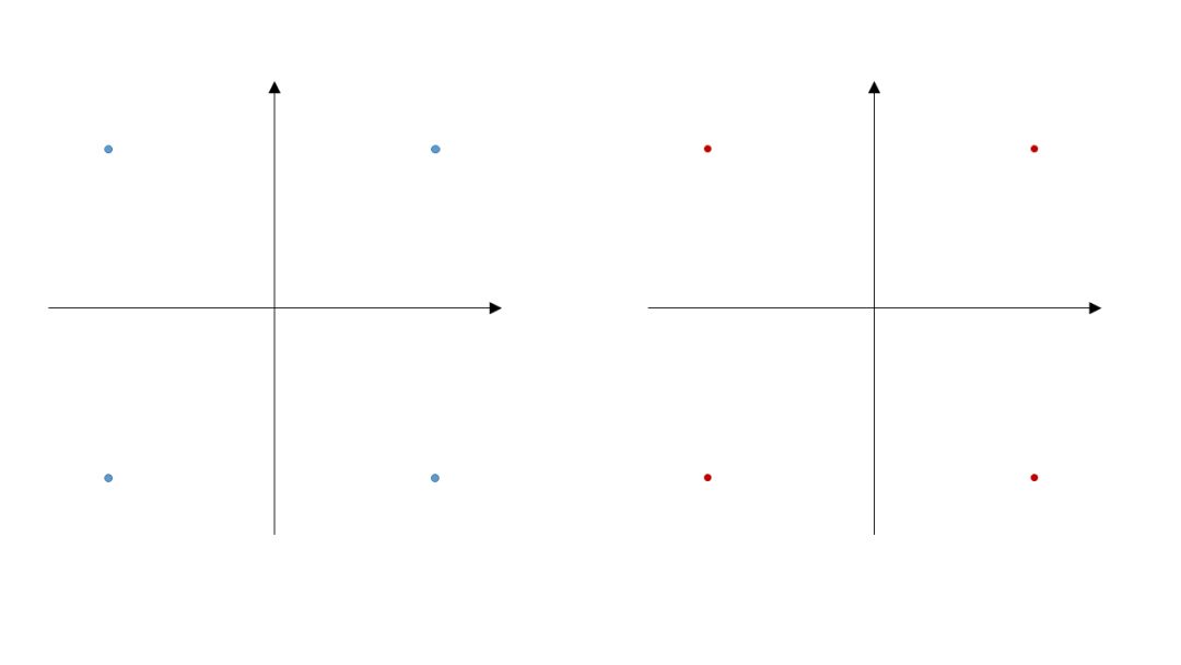 However, in practice, selecting two beams for interference presents challenges, as shown in the selectable range in Figure 2.
 The actual selection involves interpolation, as depicted in Figure 3.
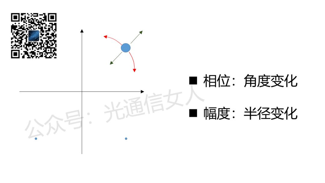
 Interpolation detection reduces the difficulty of the laser and optical phase-locked loop, but it places high demands on the DSP’s data processing capabilities, especially regarding algorithms.In addition to lowering the requirements for the light source, the optical signal experiences dispersion after long-distance transmission through fiber, including chromatic dispersion and polarization mode dispersion.These factors mix together, causing changes in phase and amplitude, as shown in Figures 4 and 5.
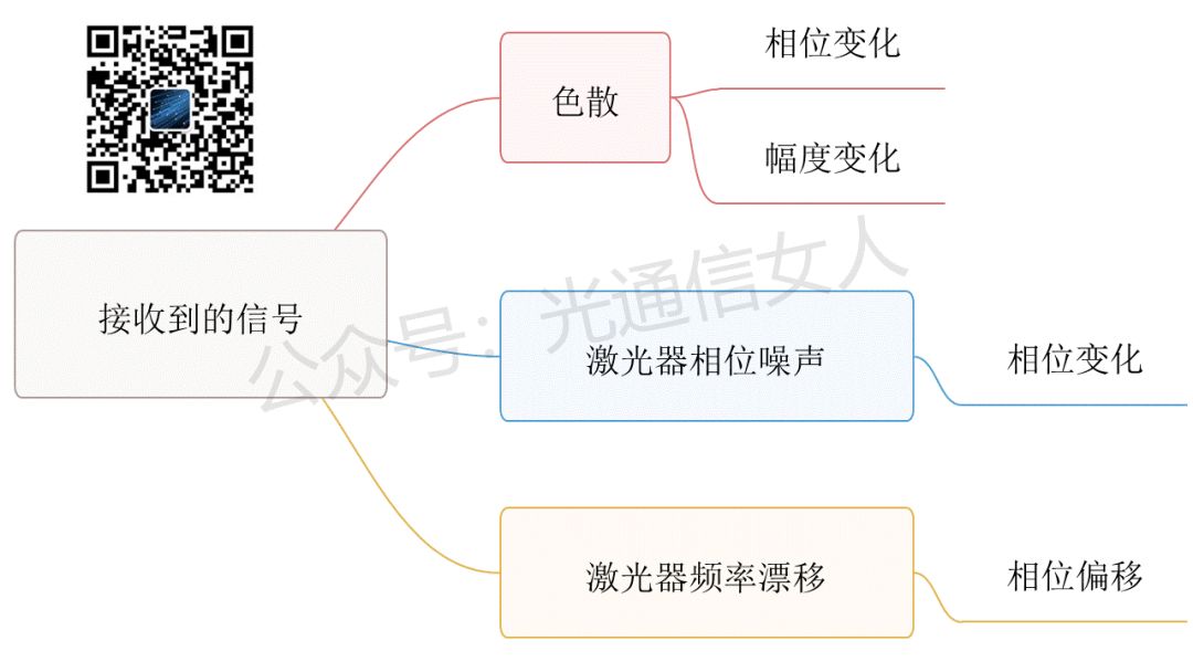
 After the optical detector receives the signal and the ADC samples it, the constellation diagram will show a multitude of points with random angles and radii, and the polarizations will be interleaved (since multiple signals need to cross for addition and subtraction).The following image illustrates the mess left for the DSP, as shown in Figure 6.
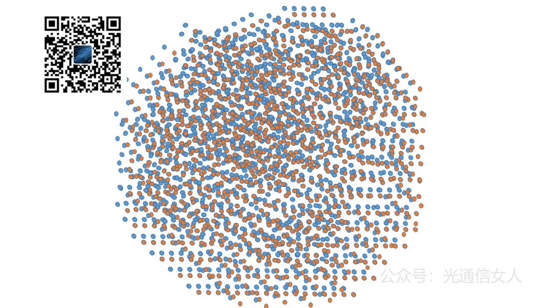 First, the DSP must perform algorithms to understand the dispersion damage of the fiber channel and know the function of the transmission channel to perform inverse compensation.This results in a swimming ring effect, as only the fiber causes amplitude variations (i.e., deviations in radius), as shown in Figure 7.
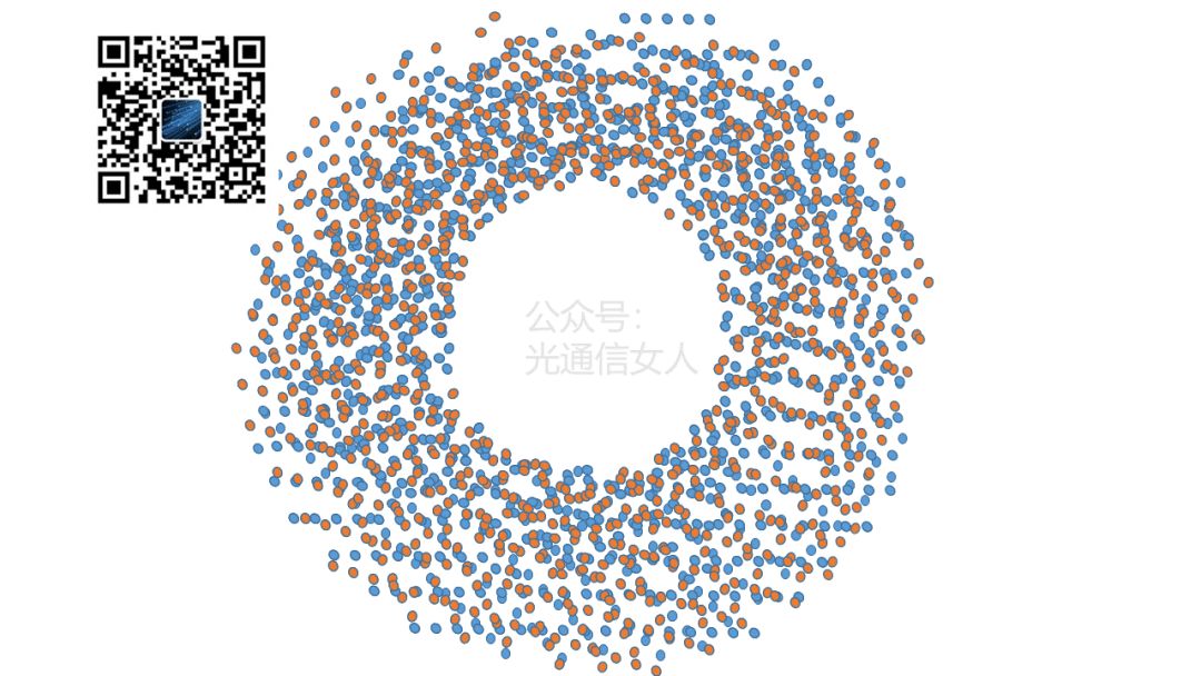 Next, the DSP separates the polarization, as shown in Figure 8.
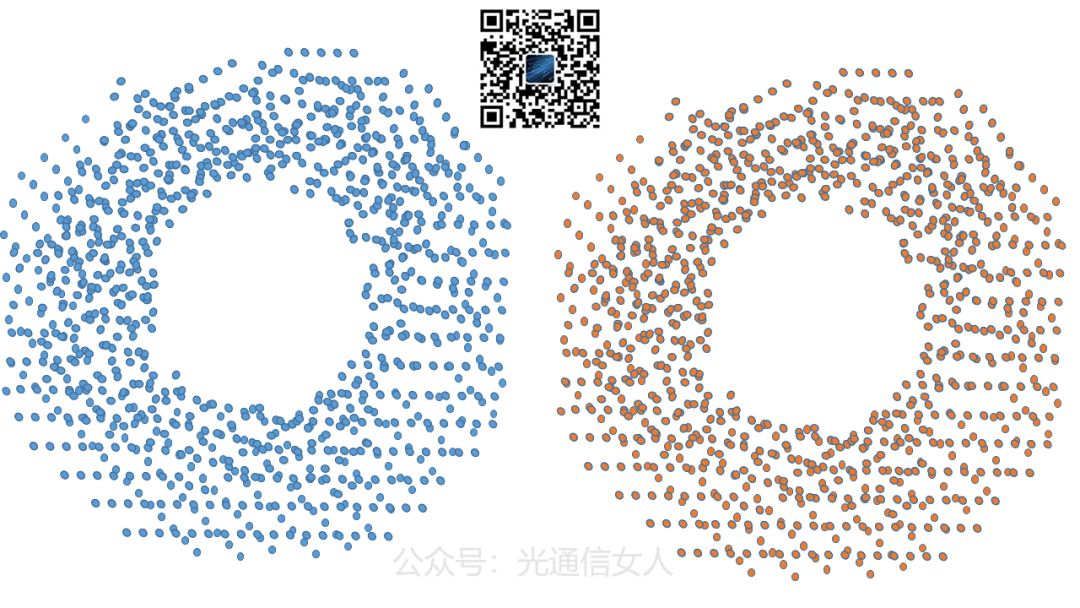 Then, the signal light and the local oscillator light source undergo interpolation detection, and the frequency offset generated by interference must be estimated by the DSP, followed by inverse computation to obtain the result shown in the following image, Figure 9.
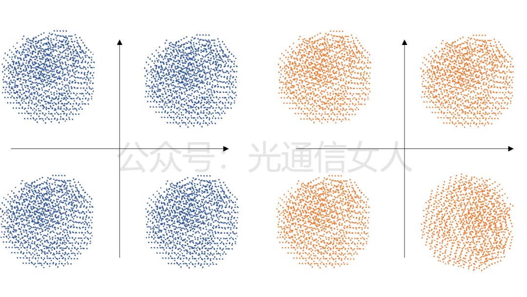 Finally, a decision is made.The challenge for DSP manufacturers lies in the algorithms.[Online Training] 22/23: Training schedule on optical transceiver module related technologies and markets.