1. Sensors
Sensors can detect physical quantities such as force, temperature, light, sound, and chemical components, and convert them into a physical quantity (usually electrical quantities like current or voltage) that is easy to transmit and process, or switch a circuit on or off.
By converting non-electrical quantities into electrical quantities, measurement, transmission, processing, and control become very convenient.
2. Principles of Sensors
Sensors typically sense non-electrical quantities such as pressure, temperature, displacement, concentration, speed, and pH.
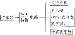
The output is usually electrical quantities, such as voltage, current, and charge, which are very weak signals and often need to be amplified before being sent to the control system to generate various control actions. The principle of sensors is illustrated in the following figures.
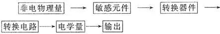
General mode of sensor application

3. Common Applications of Sensors
Photoresistor — Fire Alarm
1. The resistance of a photoresistor changes when illuminated, allowing it to convert the intensity of light into a measurable electrical quantity.
2. The resistance of the photoresistor decreases as the light intensity increases.
Photoresistors are generally made from semiconductor materials. When these materials are exposed to light or increase in temperature, more electrons gain energy to become free electrons, and more holes are formed, significantly enhancing conductivity.
Temperature Sensor Application — Electric Iron
Temperature sensors can be made from semiconductor materials or metal thermistors, converting thermal signals into electrical signals for automatic control.
(1) Structure of the Electric Iron:
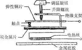
(2) Automatic Temperature Control Principle of the Electric Iron: It contains a bimetallic temperature sensor, as shown in the figure above.
At normal temperatures, the upper and lower contacts should be in contact. However, when the temperature is too high, the bimetallic strip expands differently: the upper metal expands more than the lower metal.
This causes the bimetallic strip to bend downwards, separating the contacts and cutting off the power supply to stop heating. When the temperature decreases, the bimetallic strip returns to its original state, reconnecting the circuit to heat again, thus achieving automatic temperature control.
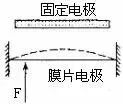
Capacitive Pressure Sensor
When the pressure F acts on the movable diaphragm electrode, it causes the diaphragm to deform, resulting in a change in capacitance.
If the capacitor is connected in series with a sensitive ammeter and power supply, forming a closed circuit, when F presses the diaphragm electrode upwards, the capacitance of the capacitor increases. The ammeter will show a reading, indicating a change in pressure F (as shown in the figure).
In comparison, metal thermistors have good chemical stability and a wide temperature range, while thermistors have better sensitivity.
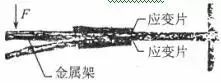
Force Sensor Application — Electronic Scale
(1) Composition: Consists of a metal frame and strain gauges.
(2) Working Principle of the Electronic Scale: As shown in the figure, the beam element made of spring steel is fixed at one end.
Strain gauges are attached to the upper and lower surfaces of the beam. When a force F is applied at the free end of the beam, it bends. The upper surface is stretched, and the lower surface is compressed, causing the resistance of the upper strain gauge to increase and the resistance of the lower strain gauge to decrease.
The greater the force F, the greater the bending deformation, resulting in a larger change in the resistance value of the strain gauges. If the current through the strain gauges is kept constant, the voltage across the upper strain gauge increases while the voltage across the lower strain gauge decreases. The sensor outputs the difference in these two voltages. The greater the external force, the larger the output voltage difference.
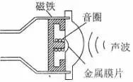
Sound Sensor Application — Microphone
(1) Dynamic Microphone Principle:
A microphone is a device that converts sound into electrical signals.
The diagram below shows the structure and principle of a dynamic microphone, which is made using the principle of electromagnetic induction.
When sound waves cause the metal diaphragm to vibrate, the coil (called the voice coil) connected to the diaphragm also vibrates.
In the magnetic field of a permanent magnet, the voice coil vibrates, generating induced current (electrical signal).
The magnitude and direction of the induced current change, with the amplitude and frequency determined by the sound wave. This signal current is amplified by a speaker and transmitted through the speaker, producing amplified sound.
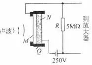
(2) Capacitive Microphone Principle:
As shown in the figure, Q is the insulating support, and the thin metal membrane M and the fixed electrode N form a capacitor that is charged by a DC power supply.
When sound waves cause the diaphragm to vibrate, the capacitance changes, creating a varying current in the circuit, thus outputting a voltage across the resistor R that corresponds to the sound changes. Its advantage is high fidelity.
(3) Electret Microphone:
① Polarization Phenomenon: When a dielectric is placed in an electric field, positive and negative charges appear on its two surfaces.
② Electret: Some dielectrics maintain their polarized state even after the external electric field is removed; these materials are called electrets.
③ Principle: Similar to the capacitive microphone, except that the sensing element is an electret plastic film.
④ Characteristics: Small size, lightweight, low cost, high sensitivity, and low operating voltage, requiring only 3-6V.
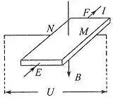
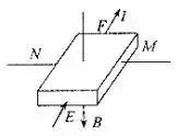
Hall Effect Device
1. As shown in the figure, a conductor plate of thickness d is placed in a uniform magnetic field with magnetic induction strength B perpendicular to it.
When a constant current I flows through the conductor plate, a potential difference appears on the left and right sides, known as the Hall effect.
By creating four electrodes EFMN on this rectangular semiconductor, it becomes a Hall device that can convert the magnetic induction strength (a magnetic quantity) into voltage (an electrical quantity).
2. Hall Voltage 
① Where k is the proportionality coefficient, known as the Hall coefficient, which depends on the material of the sheet.
② For a Hall device, d and k are fixed values. Keeping I constant, the change of is proportional to B, therefore the Hall device is also called a magnetic-sensitive device.
3. Working Principle
The Hall device is designed using the Hall effect. A rectangular semiconductor sheet has electrodes connected at its front, back, left, and right.
As shown in the figure, when current I flows along the EF direction, and a uniform magnetic field B is applied perpendicular to the sheet, a potential difference U will appear between MN. Let the thickness of the sheet be d, the length in the EF direction be l1, and the length in the MN direction be l2.
Charged particles in the sheet are deflected by the magnetic force, causing the N side to have a higher potential than the M side, resulting in an electric field inside the semiconductor, where the charged particles are also acted upon by the electric field force.
When the magnetic force and electric field force balance, the potential difference between MN reaches a constant value.

According to the microscopic explanation of current
Overall:
Let where n is the number of charged particles per unit volume of the material, and q is the charge of a single charged particle.
Thus, it can be seen that U is proportional to B, which is why the Hall device can convert magnetic quantities into electrical quantities.
End
1. After the college entrance examination, a boy kneels to thank his mother for scoring 635! Kids, be grateful to your parents whether you do well or poorly in exams.
2. Summary of college entrance examination admission scores in 24 provinces and cities in 2019, show your estimated scores!
3. These funny moments on social media will make you laugh out loud; how many have you seen?
4. It’s time to start filling in your college applications! How to choose a major? Please save this guide to the employment directions of these 12 major categories!
▐ Source:This article is compiled from various sources online. If there is any infringement, please contact us for deletion!
▐ Tags: College Entrance Examination Geography, Preparing for the College Entrance Examination, Knowledge Summary
▐ For more content, please follow our WeChat public account: College PhysicsID:gkwl100

 Click “Read the Original” to Become a Top Student!
