
When a microcontroller or FPGA sends SPI control signals to a phase-locked loop (PLL) chip, it often requires a series connection of a 22 ohm or 33 ohm resistor. What is the reasoning behind this?
Impedance discontinuities can cause electromagnetic wave reflections, which in turn can lead to signal distortion. Therefore, impedance matching is often involved in high-speed digital circuit design. However, this matching differs operationally from RF matching.
In RF matching, inductors and capacitors are typically used to reduce reflections, while in digital circuits, resistors are generally used for matching.
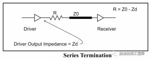
In digital circuits, source matching is one of the matching methods. The aforementioned series resistor in the signal path is a typical example of source matching. Assuming the output resistance of the digital circuit is Zd and the characteristic impedance of the transmission line is Z0, the series resistor R can be calculated as R = Z0 – Zd.
It has been mentioned in forums (1) that the output resistance of digital circuits can be calculated using Zo = (Vdd – VOH) / IOH and Zo = VOL / IOL. However, in practice, this is not always ideal.
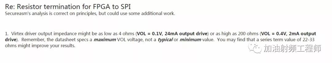
As noted in (2), even for the same model of device, the values can vary significantly.
Therefore, in practical applications, it is advisable to leave a space in the circuit to change the resistor values while using an oscilloscope to test when the ringing in the waveform disappears.
References:
(1)https://www.physicsforums.com/threads/how-to-determine-the-output-impedance-of-cmos-gates.433643/
(2)https://forums.xilinx.com/t5/General-Technical-Discussion/Resistor-termination-for-FPGA-to-SPI/td-p/160122
Hello everyone, I am Board Brother!
The new disassembly activity of the Breadboard Community has launched, with prizes available (such as oscilloscopes, sports/panoramic cameras, high-definition infrared thermal imaging cameras; DJI Neo tracking drone, Raspberry Pi 5, Fluke digital multimeter, etc.), and there are rewards just for participating, so fans, let’s get disassembling!
Activity Details👉The first disassembly activity of the Breadboard Community in 2025 is here~~~

Recommended Reading
Disassembling a highly optimized voice recorder: a typical and outstanding low-power design solution
2025-04-28
Why does the MCU communication have a mid-level voltage?
2025-04-28
The secrets revealed only after disassembly—why does this Philips LED lamp (10 pieces) often warp?
2025-04-27
Basic knowledge of stepper motors: types, uses, and working principles
2025-04-27
What to do if the layout of a single-layer PCB with QFN package cannot route the middle ground pad?
2025-04-26
[Disassembly] iCreate USB flash drive hard chip disassembly: a clever design to reduce costs!
2025-04-25
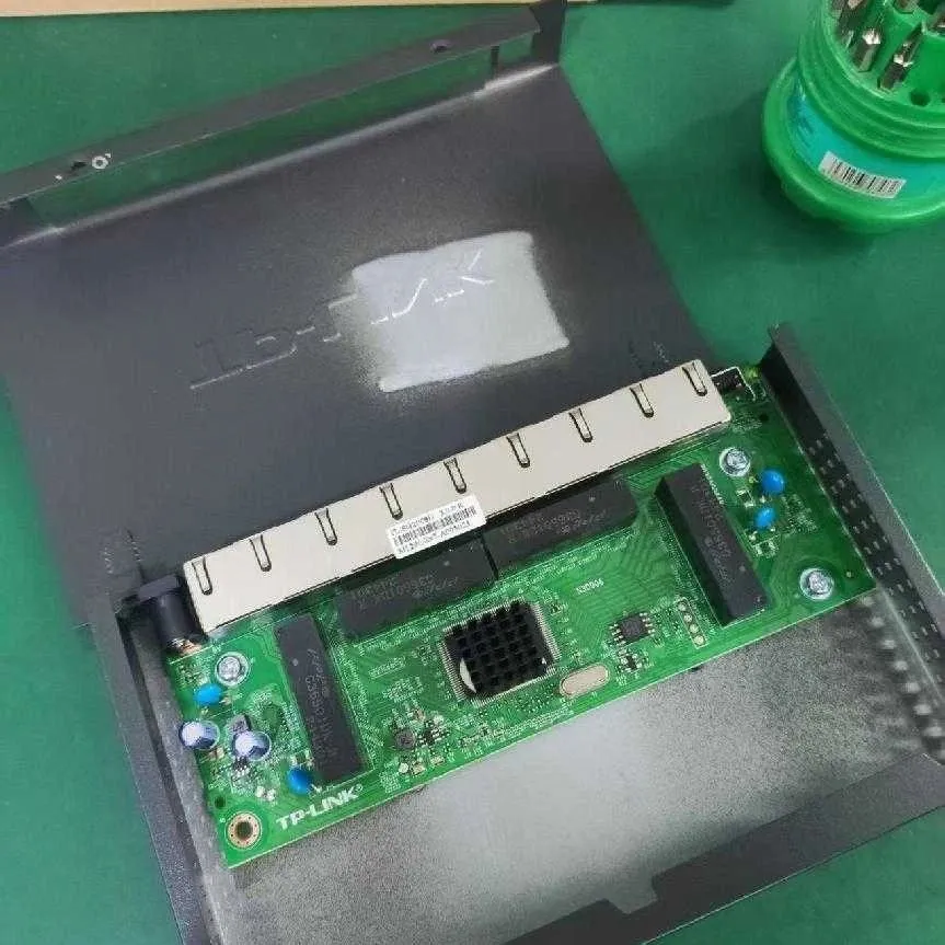
Excellent thermal design! Disassembling TPLIN’s 8-port gigabit metal shell cloud switch
2025-04-24
[Disassembly] Exclusive! Complete record of Huawei VR cooling back clip disassembly and repair
2025-04-23