To not miss exciting content, please set “Measurement Information Express” as a starred ☆.
1. Entering Adjustment Mode
To prevent unauthorized adjustments, specific steps must be followed to enter the adjustment mode. The method may vary among different models of oscilloscopes. Common methods to enter adjustment mode include:
1. Calibration Switch
For the Tektronix TDS200 series, the method to enter adjustment mode is: while the oscilloscope is powered on, use a tool to press the calibration hole button on the back panel of the oscilloscope, while simultaneously pressing the “Utility” button on the front panel, then you can enter the service menu for adjustment operations.
For the Tektronix TDS3000 series, the method to enter adjustment mode is: while pressing the power button to start the oscilloscope, keep pressing the calibration hole button on the back panel until the oscilloscope has fully started, then release the back panel calibration button. At this point, you can enter the adjustment mode through the “CAL” submenu under the “Utility” menu.
2. Specific Keys
For the Tektronix TDS2000C series, the method to enter adjustment mode is: while powered on, press the “Measure” button on the front panel to enter the measurement menu, press the top option button to enter the “Measure 1” submenu, hold down the “Single” button on the front panel, then press and hold the “Auto Set” button, wait at least 2 seconds, release the “Single” button, and then release the “Auto Set” button to enter the service menu for adjustment operations.
For the Tektronix DPO2000 series, the method to enter adjustment mode is: after warming up, press the “Utility” button on the front panel, then select the “Calibration” submenu, and choose the “Manufacturer Pass” menu through the software, at which point a dialog box indicating manufacturer calibration pass will appear. Press and hold the top right button on the screen (located below the “waveform only” button) for about 5 seconds to enter the manufacturer adjustment mode.
2. Introduction to Adjustment Items
1. DC Voltage
This adjustment item usually uses a DC standard voltage source to input DC voltage signals to all measurement channels simultaneously. A typical wiring method is shown in Figure 1.
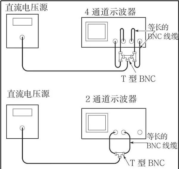
Figure 1 DC Voltage Adjustment Wiring Diagram
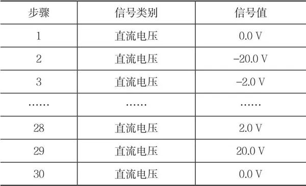
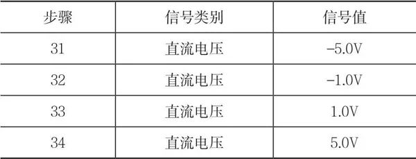
Taking the TDS2000C oscilloscope as an example, there are a total of 30 items for DC voltage adjustment, as shown in Table 1.
It should be noted that to ensure the effectiveness of the adjustment, the calibration connection wires for each channel should preferably use equal-length cables, and the connection wires should not be too long (about 25 cm is appropriate).
Some steps require setting the input voltage to 0.0000 V, and some voltage sources may introduce noise or small AC signals when outputting a 0V signal. In such cases, the instrument may still fail the performance verification test after the adjustment program. When the oscilloscope prompts for an input of 0.000 V, all signal lines can be removed from the oscilloscope (i.e., the oscilloscope is not connected to any signal lines).
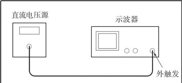
2. External Trigger Voltage
This adjustment item usually uses a DC standard voltage source to input DC voltage signals to the external trigger terminal of the oscilloscope. A typical wiring method is shown in Figure 2.
Taking the TDS2000C oscilloscope as an example, there are a total of 4 items for external trigger voltage adjustment, as shown in Table 2.
3. AC Voltage
This adjustment item usually uses a sine wave signal generator to input sine signals of specified voltage and frequency to the measurement channels of the oscilloscope. A typical wiring method is shown in Figure 3.
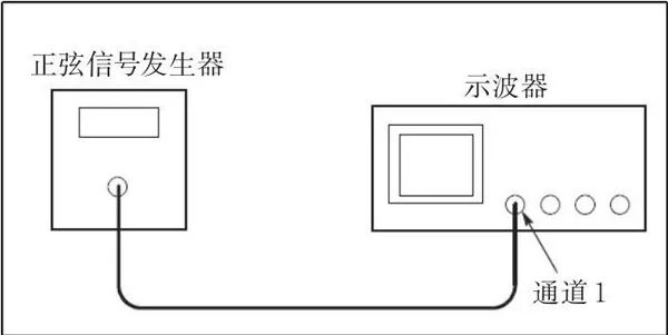
It should be noted that during this adjustment item, the output impedance of the sine wave signal generator should usually be set to 50Ω; some oscilloscopes require a 50Ω matching resistor to be connected at the oscilloscope input, such as the TDS200 and TDS2000C series; while some oscilloscopes do not require a matching resistor, such as the TDS3000 series. However, some oscilloscopes require the output impedance of the sine wave signal generator to be set to 1MΩ, which should be based on the requirements of each oscilloscope’s service manual.
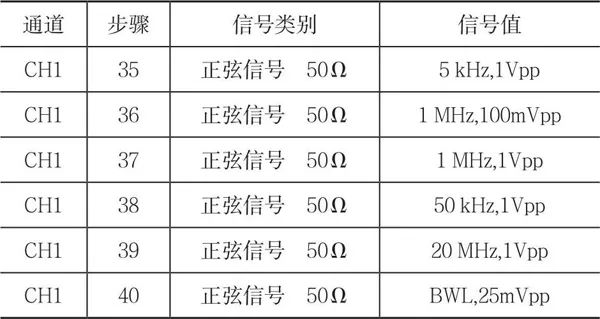
Taking the TDS2000C as an example, the typical adjustment steps are shown in Table 3, where “BWL” refers to the bandwidth of the oscilloscope.
4. Fast Edge
This adjustment item usually uses a fast edge pulse signal generator to input signals to the specified channel of the oscilloscope.
For the TDS2000C, if the oscilloscope has 2 channels, a fast edge pulse signal with a frequency of 1kHz and a voltage of 0–800mV should be input to channel 1; if the oscilloscope has 4 channels, fast edge pulse signals should be input to channel 1 and channel 3 respectively. During the adjustment, the output impedance of the fast edge signal generator should be set to 50Ω, and a 50Ω matching resistor should be connected at the oscilloscope input.
For the TDS3000 series, a fast edge pulse signal with a frequency between 100Hz and 1MHz and a voltage of -2.2 V to 0 V should be input to each channel, with a rise time of less than or equal to 1ns. During the adjustment, the output impedance of the fast edge signal generator should be set to 50Ω, and no 50Ω matching resistor is required at the oscilloscope input.
The above calibration adjustment methods have been practically verified by the author and are feasible, serving as a reference for oscilloscope calibration personnel and maintenance personnel.

This article was published in the 2020 issue 7 of “Chinese Metrology” magazine
Author: Liu Jia and Song Dan, CRRC Zhuzhou Electric Co., Ltd.