Source: Keysight Technologies
Abstract:The demand for higher bandwidth and lower latency in autonomous vehicles and advanced driver assistance systems (ADAS) has become more urgent. In-vehicle Ethernet has emerged as the new backbone for building high-speed automotive networks. Comprehensive testing of transmitters, receivers, link segmentation, and higher-layer protocol functions ensures successful implementation.
The main drivers of innovation in the automotive industry can be divided into three categories: enhanced safety, environmental protection, and increased convenience through interconnectivity. To achieve these goals, automotive manufacturers, suppliers, governments, academia, and even companies outside the traditional automotive sector (such as wireless chip manufacturers, mobile device manufacturers, and wireless service providers) are all working hard to develop advanced driver assistance systems (ADAS), connected car technologies, and ultimately, fully autonomous vehicles.
ADAS and autonomous vehicles require a high-bandwidth and low-latency network to connect all sensors, cameras, diagnostic tools, communication systems, and central artificial intelligence.
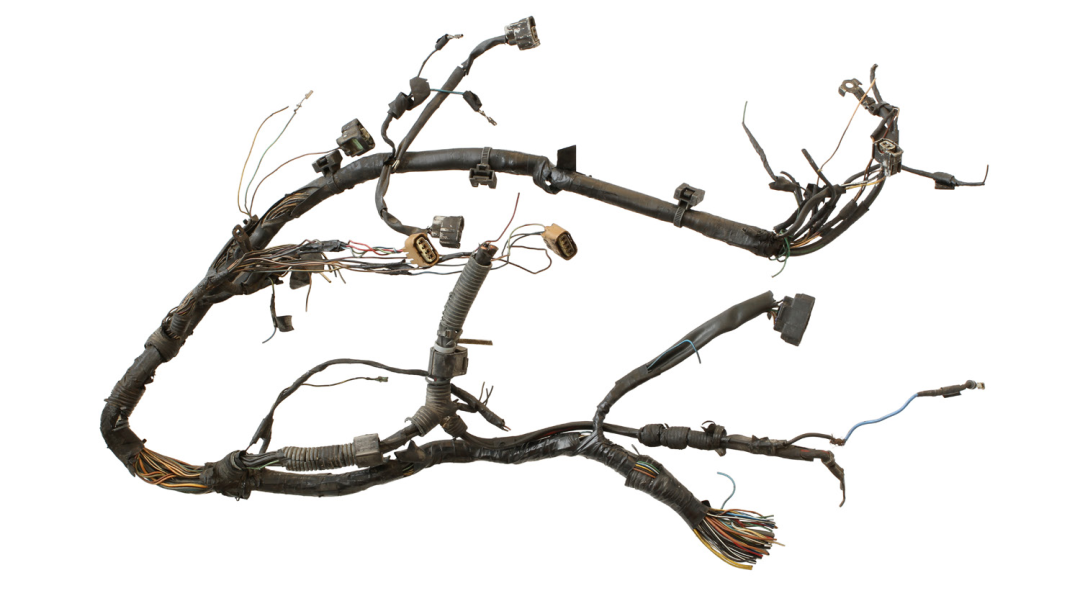
Currently, wiring harnesses rank third among all automotive components in terms of weight and cost. The installation of wiring harnesses accounts for 50% of labor costs during vehicle assembly.
In-vehicle Ethernet is an emerging solution to these challenges. Just as WiFi is the cornerstone of dedicated short-range communication (DSRC), Ethernet is a well-known, trusted, and widely used solution in traditional local area networks (LAN). Ethernet offers many advantages, such as multi-point connectivity, wider bandwidth, and low latency, which are highly attractive to automotive manufacturers. However, traditional Ethernet generates too much noise and is easily interfered with when used in vehicles. To meet the specific needs of the automotive industry, the IEEE has established new standards and protocols.
Autonomous Driving Requires Faster Data Acquisition and Processing
The technologies used in autonomous vehicles employ numerous new electronic components. The first category supports sensor fusion in radar (RADAR), light detection and ranging (LIDAR), and cameras. The second category includes wireless communications such as vehicle-to-vehicle (V2V), vehicle-to-network (V2N), vehicle-to-infrastructure (V2I), vehicle-to-pedestrian (V2P), vehicle-to-utility (V2U), and vehicle-to-everything (V2X). Various adjacent components, such as high-definition (HD) maps with high-precision navigation systems, powerful signal processing, and artificial intelligence, are essential for autonomous driving.
These technologies generate, send, receive, store, and process massive amounts of data. For example, a LIDAR module can provide high-precision, high-resolution three-dimensional and 360° imaging data around the vehicle. A LIDAR module may generate 70 Mbps of data traffic, a camera may generate 40 Mbps, a RADAR module may generate 100 Kbps, and a navigation system may generate 50 Kbps.
Moreover, the higher the level of the autonomous driving system, the greater the number of independent sensors, leading to an even larger total data volume. For instance, a Level 2 autonomous driving system can provide longitudinal and lateral vehicle motion control, allowing the driver to take their hands off the wheel and temporarily rest their eyes. This system may require 5 RADAR sensors and 5 cameras. Fully autonomous driving systems (Level 4 and Level 5) will require up to 20 RADAR sensors and 6 cameras, as well as V2X communication. We predict that an autonomous vehicle will generate approximately 4 TB of data per day. This data needs to be transmitted, stored, and shared over high-speed, reliable networks with extremely low latency, which is precisely where the high throughput and low latency of in-vehicle Ethernet excels.
Overview of Automotive Serial Buses
By reviewing the major traditional automotive serial buses, including CAN, LVDS, LIN, MOST, FlexRay, and CAN FD, we can better understand why autonomous vehicles and advanced driver assistance systems now require in-vehicle Ethernet.
CAN (Controller Area Network) – 1983
CAN is a shared serial bus developed by Bosch, with a transmission rate of up to 1 Mbps. CAN was later approved by ISO and became an international standard. Its advantages are cost-effectiveness and high reliability. However, its drawbacks include shared access and lower bandwidth. CAN is mainly used in powertrain, chassis, and body electronics.
LVDS (Low-Voltage Differential Signaling) – 1994
LVDS is a point-to-point link, not a shared bus. It is much cheaper than MOST (Media Oriented Systems Transport), and many automotive manufacturers use it to transmit camera and video data. However, each LVDS link can only connect one camera or video output at a time.
LIN (Local Interconnect Network) – 1998
LIN was developed by an alliance of automotive manufacturers and technology partners. Its rate is only 19,200 bits per second and requires only one shared line, while CAN requires two. LIN uses a master-slave architecture, while CAN treats all nodes as equal. LIN is cheaper than CAN, and its speed and cost are just right for body electronics such as mirrors, power seats, and accessories.
MOST (Media Oriented Systems Transport) – 1998
MOST uses a ring architecture, interconnected by optical fibers or copper cables, with data rates of up to 150 Mbps (MOST150). Each ring can contain 64 MOST devices. The advantage of MOST for the automotive market is relatively high bandwidth, but its cost is also quite high. It was initially only suitable for camera or video connections.
FlexRay – 2000
FlexRay is a shared serial bus with a data rate of up to 10 Mbps. It was developed by the FlexRay Consortium, an organization established by semiconductor manufacturers, automotive manufacturers, and infrastructure providers. Unlike CAN, it does not have built-in error recovery, leaving error handling to the application layer. Its advantage is higher bandwidth than CAN, but its disadvantage is higher cost and the need for shared media. FlexRay is mainly used in high-performance powertrains and safety systems, such as steer-by-wire, active suspension, and adaptive cruise control.
CAN FD (Flexible Data Rate) – 2012
CAN FD is a standard released by BOSCH in 2012, which is an extension of the original CAN bus protocol. It was designed to meet the automotive network’s demand for higher bandwidth. CAN FD achieves more precise and near-real-time data transmission by minimizing protocol delays and providing higher bandwidth. CAN FD is compatible with existing CAN networks.
In-Vehicle Ethernet
Although traditional automotive serial buses have played an important role in various automotive applications, they also have their drawbacks, which in-vehicle Ethernet can overcome. For example, most automotive serial buses cannot reach the 70 MB/s data rate required by LIDAR. When various sensing technologies and wireless communication technologies are integrated, it often requires the simultaneous use of LIDAR, RADAR, cameras, and V2X communication. In these cases, the amount of data to be transmitted exceeds the existing capacity of traditional automotive serial buses. Therefore, the automotive industry wants to introduce in-vehicle Ethernet to make autonomous driving and advanced ADAS systems a reality.
What is In-Vehicle Ethernet?
In-vehicle Ethernet is a wired network that connects electronic components in vehicles. It is designed to meet the automotive industry’s requirements for bandwidth, latency, synchronization, interference (e.g., electromagnetic interference (EMI)), security, and network management. The concept of in-vehicle Ethernet was initially proposed by Broadcom, and later adopted by the OPEN (Single Pair Ethernet) Alliance, which took on management responsibilities. OPEN promotes Broadcom’s 100 Mbps BroadR-Reach as a multi-vendor licensed solution. The 100 Mbps PHY implementation draws on 1 Gbps Ethernet technology, achieving 100 Mbps bidirectional transmission over a single pair of cables. This technology uses more advanced coding schemes to eliminate echoes, reducing the fundamental frequency (from 125 MHz) to 66 MHz, allowing Ethernet to meet automotive EMI specifications. The IEEE and OPEN Alliance have established and are responsible for maintaining the physical layer standards for 100 Mbps and 1000 Mbps in-vehicle Ethernet in IEEE 802.3 and 802.1 groups.
In the early stages, Ethernet had only one 100Base-T1 1TPCE link from the DLC diagnostic port to the gateway, so it was only used for diagnostics and firmware updates. Figure 1 shows the evolution of in-vehicle Ethernet as a new backbone (using faster gigabit Ethernet 1000Base-T1 RTPGE links).
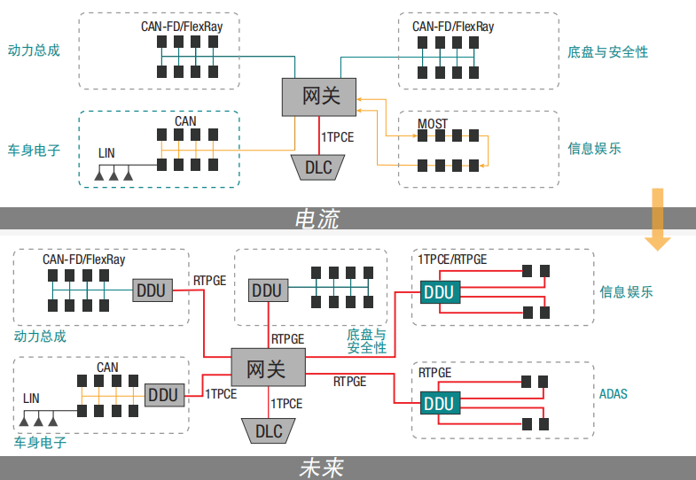
Figure 1: Evolution of In-Vehicle Ethernet
Why Choose In-Vehicle Ethernet?
In terms of connectivity and communication for automotive electronic systems, autonomous driving, and ADAS systems, in-vehicle Ethernet has clear advantages over traditional automotive serial buses. The architecture of automotive electronics is becoming increasingly complex, with more sensors, controllers, and interfaces, requiring higher bandwidth, more computing power, and communication links. The wiring harnesses connecting these systems rank third among all automotive components in terms of weight and cost. Currently, automotive manufacturers use various proprietary standards to provide communication functions; most components use a dedicated line or cable. In-vehicle Ethernet is a unified standard that supports all communications. It uses a pair of cables to connect each electronic component to a central network switch. A joint survey conducted by Broadcom and Bosch shows that by using unshielded twisted pair (UTP) cables and smaller compact connectors, connection costs can be reduced by up to 80%, and cable weight can be reduced by up to 30%.
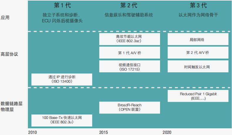
Figure 2: Development Process of In-Vehicle Ethernet
Evolution of In-Vehicle Ethernet Technology
The advancements shown in Figure 2 are attributed to progress in several technological areas, including:
AUTOSAR (Automotive Open System Architecture)
AUTOSAR is an open and standardized automotive software architecture. It was jointly developed by automotive manufacturers, suppliers, and tool developers. AUTOSAR includes a TCP/IP protocol model used in vehicles. The automotive industry has reached a consensus to establish AUTOSAR as a standard, allowing automotive manufacturers to compete at the implementation level without disputing the standard itself. The implementation of this standard will enable multiple devices to operate seamlessly on a shared network.
Single Pair Ethernet (OPEN)
Broadcom developed BroadR-Reach as a proprietary physical layer standard that supports longer distances for 100 Mbps copper Ethernet connections. This standard adopts gigabit Ethernet copper cable technology at the physical layer, including multi-level PAM-3 signaling and better coding schemes, reducing the bandwidth required by the cable. It also uses echo cancellers to achieve bidirectional data transmission over a single pair of cables. The bandwidth of this standard is 27 MHz, which is smaller than the 62.5 MHz bandwidth of the 100Base-T standard, thus meeting automotive EMI requirements. OPEN SIG has developed a licensed open standard that is supported by mainstream manufacturers in the automotive market. The industry has recognized that 100 Mbps is sufficient for video transmission but is still not enough to serve as the backbone in vehicles, particularly to meet the demands of ADAS and autonomous driving systems. Therefore, the IEEE 802.3 working group (802.3bp) has formed a group tasked with defining a new standard for achieving 1000 Mbps (1 Gbps) data rates over a single pair of twisted wires. This gigabit Ethernet physical layer standard is known as 1000Base-T1 (1 represents 1 pair).
Time Synchronization
Some automotive algorithms require multiple sensors to sample simultaneously or use the time of measurement as a reference time. Since these measurements are taken at different nodes, all nodes in the vehicle must achieve sub-microsecond precision time synchronization. The IEEE 802.1AS timing and synchronization standard for bridging time-sensitive applications in local area networks has been selected as the synchronization timing standard. This standard uses a profile of IEEE 1588 v2 and introduces a simplified method for faster selection of the master clock.
Time-Triggered Ethernet
Some time-sensitive controls require communication delays of less than 1 microsecond so that controllers can quickly obtain sensor readings or control functions that are highly time-sensitive. In traditional Ethernet, packets must be transmitted one by one, and even at gigabit speeds, transmitting a single packet can take hundreds of microseconds. The IEEE 802.3br (Interspersed Express Traffic) working group is developing a system to address this issue, where high-priority packets (called Express packets) can interrupt the transmission of existing packets for priority transmission, and once the transmission is completed, the interrupted packets continue to be transmitted.
AV Bridging
ADAS primarily relies on timely data acquisition from cameras and other sensors. While video can be buffered on a computer to address unreliable network timing, automotive AV systems cannot do this; they need to control both latency and guarantee bandwidth simultaneously. The Time-Sensitive Networking Task Group has established corresponding specifications to support low-latency data flow services with time synchronization.
Comprehensive Testing Requirements for Successful Implementation
In-vehicle Ethernet engineers need to address common high-frequency circuit board design issues, including signal noise, signal integrity, crosstalk, reflections, impedance matching, and DC power integrity. To ensure successful implementation and reliable operation, in-vehicle Ethernet also requires comprehensive testing of the physical layer, protocols, compliance, security, and wiring harnesses. The physical layer compliance testing has three test points (Figure 3): transmitter and protocol triggering and decoding; link segmentation, including wiring harnesses and connectors; and receiver.
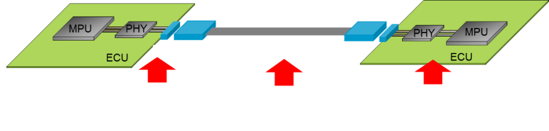
Figure 3: Physical Layer Testing Points for In-Vehicle Ethernet
Transmitter Testing
Transceiver testing is similar to physical layer characterization solutions for other high-speed digital standards. Engineers must select a testing solution that includes a protocol triggering and decoding software package, which will examine data traffic and protocol layer dynamics, thus saving debugging time for early designs. All necessary compliance testing needs to be pre-packaged in the setup, configuration, and reporting stages so that designers can focus on their core tasks and complete work on time.
 Receiver TestingA powerful 100Base-T1 receiver (RX) compliance testing application software should automatically configure all necessary testing equipment, simplifying and speeding up the entire testing process. This software also provides Bit Error Rate Testing (BERT or BER testing).• Simplified receiver compliance testing• Automatic configuration of all necessary equipment, reducing testing time• Graphical display of connections with the device under test• Generation of HTML format and printable pass/fail test reports, including margin analysis resultsLink Segmentation TestingA complete link segmentation compliance testing solution needs to support cable testing, connector testing, communication channel testing, connector crosstalk testing, and crosstalk testing across the entire communication channel.Higher Layer Protocol TestingIn-vehicle Ethernet requires not only physical layer testing. Verification solutions also require higher-level testing methods, including the automotive TCP/IP protocol model, time synchronization (IEEE 802.1AS), audio-video bridging transmission (802.1Qav), and scheduled traffic transmission (IEEE 802.1Qbv) protocol implementation. The following Figure 4 shows the complete protocol model for in-vehicle Ethernet.
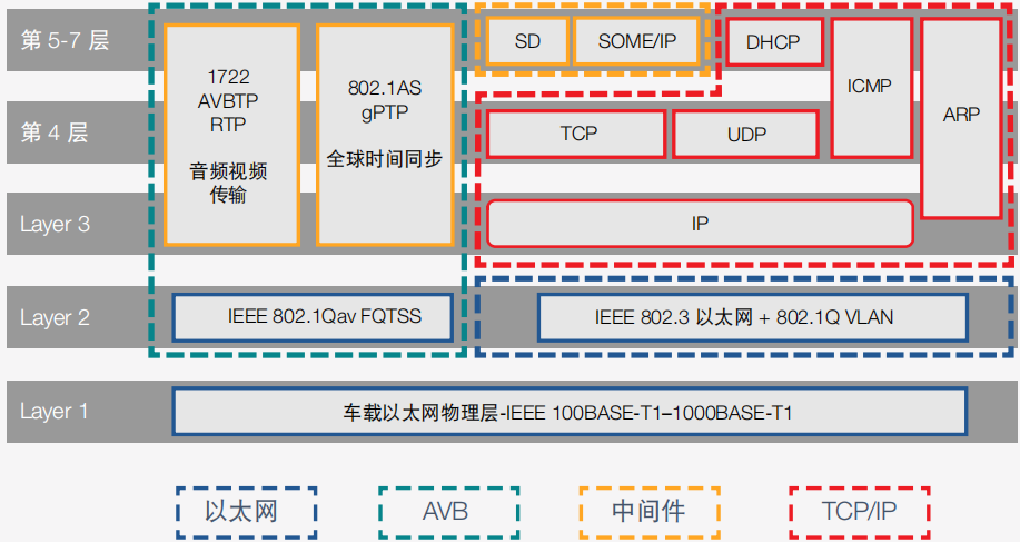 Figure 4: Complete Model of In-Vehicle EthernetIn-Vehicle Ethernet is the Future of Advanced Driver Assistance SystemsAutonomous driving and ADAS will benefit society but also bring many new testing challenges for engineers. Currently, the automotive demand for high data rates, bandwidth, and data security continues to rise, while also requiring better preparation to meet future demands. In-vehicle Ethernet provides the necessary advanced features and overcomes the shortcomings of traditional automotive serial buses in terms of connectivity and communication for automotive electronic systems. Keysight Technologies offers high-performance solutions that help engineers comprehensively test transmitters, link segmentation, receivers, and higher-layer protocol functions, ultimately ensuring successful implementation of in-vehicle Ethernet.Welcome to All Automotive Industry Chain (Including Electrification Industry Chain) Angel Round,ARound Enterprises to Join(Friendly connections with 700 automotive investment institutions, including top-tier organizations; some quality projects will be selected for themed roadshows to existing institutions); There are communication groups for leaders of innovative technology companies,, automotive industry complete vehicles, automotive semiconductors, key components, new energy vehicles, intelligent connected vehicles, aftermarket, automotive investment, autonomous driving, vehicle networking, and dozens of other groups. Please scan the administrator’s WeChat to join the group (Please indicate your company name)