🤞Hello everyone, this is a sharing of the 5132 microcontroller graduation project. Today, I will share with you the “Smart Pet Monitoring System Based on STM32”. Contact: lwfw123456789
1. Physical Display
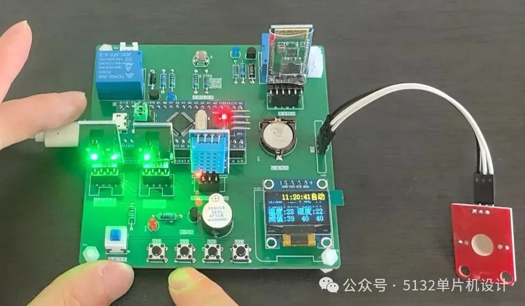
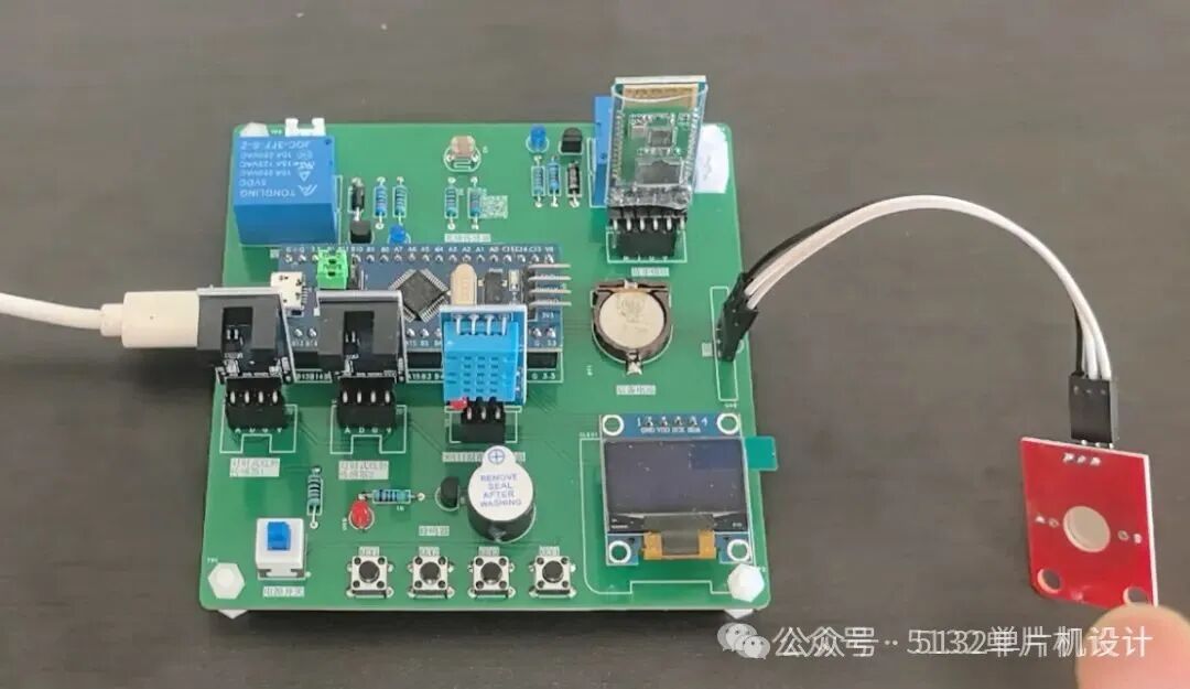
2. Function Introduction
2.1 Hardware List
- 1. STM32F103C8T6 Minimum Core Control Board
- 2. WiFi Module
- 3. Relay (2 units)
- 4. Fan Module
- 5. Water Level Sensor
- 6. Servo
- 7. Supplementary Light
- 8. Infrared Sensor
- 9. DHT11 Temperature and Humidity Sensor
- 10. Display Screen
- 11. Photoresistor
- 12. Buzzer
2.2 Function Description
The smart pet monitoring control system based on STM32F103C8T6 as the main controller has the following functions:
- 1. STM32F103C8T6 Minimum Core Control Board: Serves as the core control unit of the system, responsible for coordinating and controlling the operation of the entire smart pet monitoring system.
- 2. WiFi Module: Used to connect to the network, enabling remote control of the device via a mobile app, allowing users to operate and monitor the system remotely.
- 3. Relay (2 units): Controls heating and water replenishment functions. When the system needs heating or water replenishment, the relay activates, connecting the corresponding circuit to perform the operation.
- 4. Fan Module: Functions to dehumidify the system. For example, when humidity exceeds the set threshold, the fan automatically starts to dehumidify; in manual mode, the fan can also be controlled directly via buttons.
- 5. Water Level Sensor: Used to detect whether there is water inside. When the water level is below the set threshold, the system triggers a water replenishment operation.
- 6. Servo (Simulated Feeder): Used to simulate feeding actions. When the system detects that there is no food, the servo activates to dispense food to meet the pet’s dietary needs.
- 7. Supplementary Light: Used for environmental lighting. In automatic mode, when the light intensity is below the set threshold, the supplementary light automatically turns on; when the light intensity exceeds the threshold, the supplementary light turns off.
- 8. Infrared Sensor: Used to detect whether there is food. When no food is detected, the system triggers an alarm and controls the servo to dispense food.
- 9. DHT11 Temperature and Humidity Sensor: Used to detect the temperature and humidity of the environment and upload the detected data to the mobile app, allowing users to understand the environmental temperature and humidity in real-time.
- 10. Display Screen: Used to display various information of the system, including temperature, humidity, light intensity, water level sensor data, and system working modes.
- 11. Photoresistor: Used to detect light intensity, with the detection result used to control the on/off of the supplementary light.
- 12. Buzzer: Used for sound alarms. When the system detects abnormal situations such as no food, the buzzer will emit an alarm sound to alert the user.
2.3 Working Modes
1. Remote Mode
- • Remote control of the device via mobile app
- • Real-time acquisition of temperature/humidity/light/water level data streams
2. Manual Mode
- • Button 1 → Control heating
- • Button 2 → Control water replenishment
- • Button 3 → Control fan
3. Automatic Mode
| Trigger Condition | Action Executed |
|---|---|
| Light intensity < threshold | Turn on supplementary light |
| Temperature < threshold | Activate heating module |
| Humidity > threshold | Activate fan for dehumidification |
| Infrared sensor detects no food | Buzzer alarm + Servo feeding |
4. Threshold Settings
Enter the settings interface via buttons to dynamically adjust the trigger thresholds of each sensor (button increment/decrement operation).
3. Software Design Flowchart
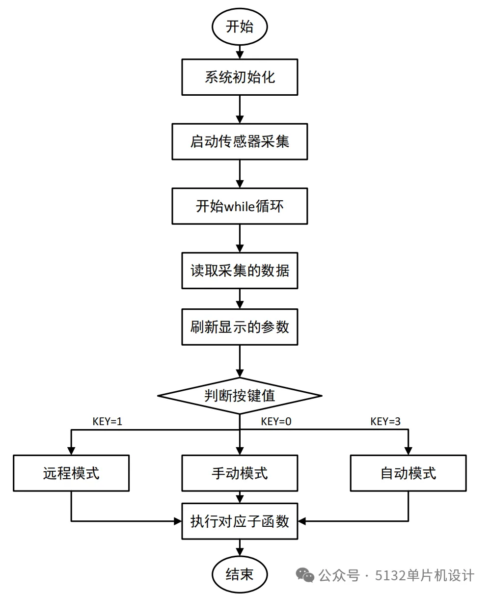
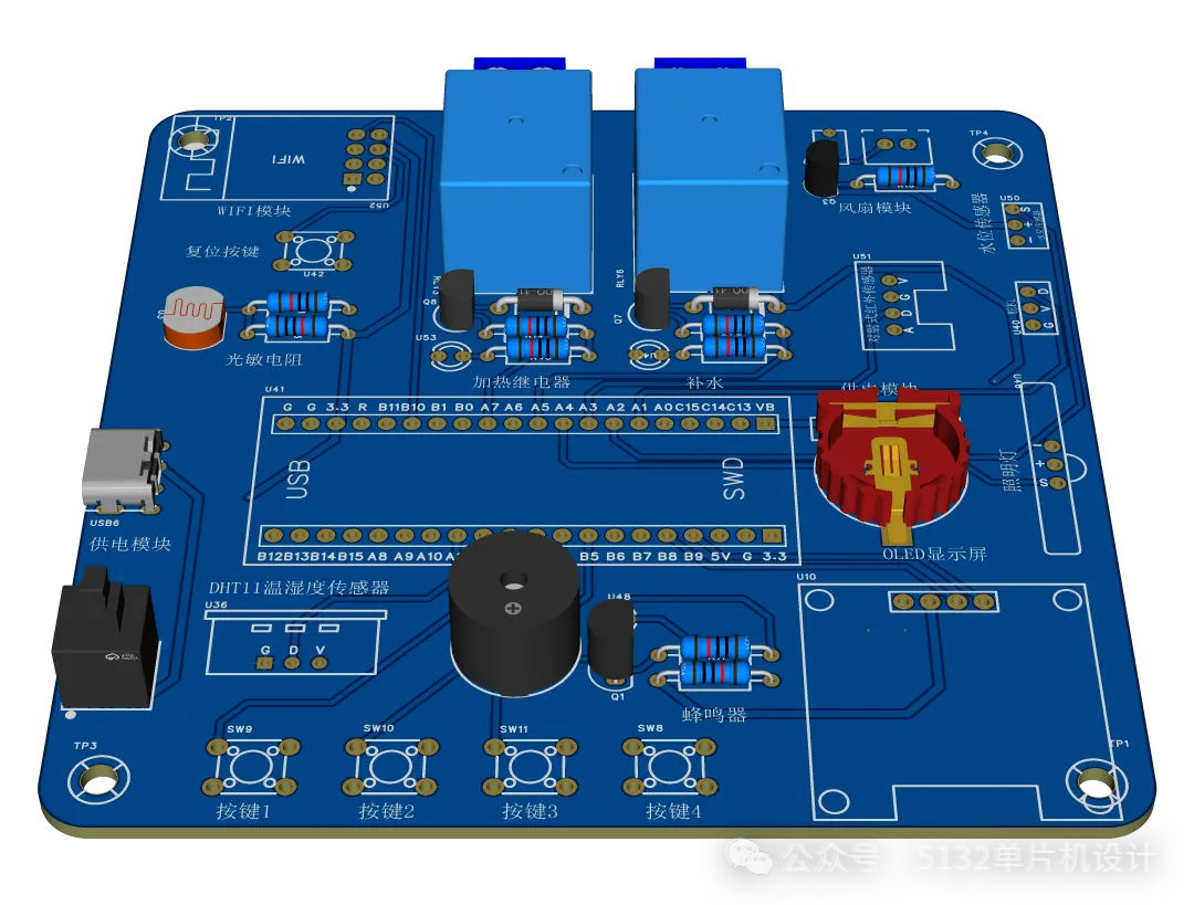
4. Schematic Diagram Display
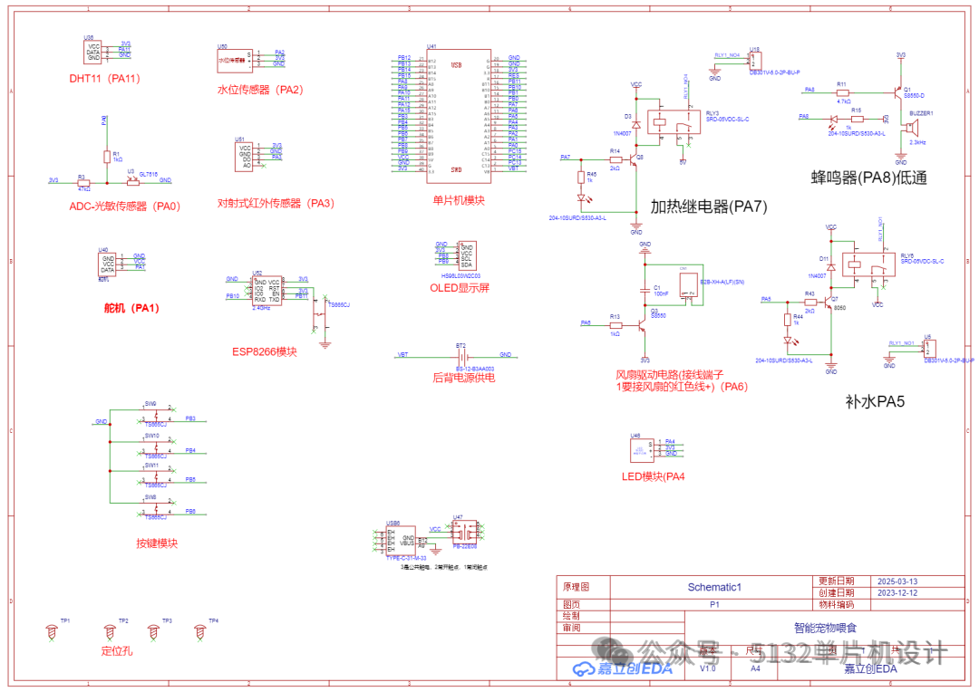
5. Part of the Program Display
The control mode and logic of the main program:
#include"main.h"

uint8_t KeyNum;// Store key value
u8 t = 0;// Sensor reading time interval
uint16_t RTC_Time[] = {0, 0, 0};// RTC time
uint16_t RTC_Time1[] = {7, 0, 0};// Timer time---on
uint16_t RTC_Time2[] = {19, 0, 0};// Timer time---off
u8 S_Mode; // Key state flag
u8 S_Shou_1, S_Shou_3;     // Manual mode control device 1
u8 S_Shou_2;     // Manual mode control device 2
u8 S_YuZhi;       // Used in threshold settings, to switch thresholds
// Other state flags
u8 qingping = 1;   // Clear screen flag
u8 S_ShiShi_Time_1;     // Used to set real-time time, to switch time display and set time
u8 S_ShiShi_Time_2;    // Used to set real-time time, to switch set hours, minutes, and seconds
u8 S_DingShi_Switch;    // Used in setting timer time, to switch hours, minutes, and seconds

// Define sensor data and threshold structure variable
SensorDataAndThreshold sensorData;

// Initialize related hardware and Gizwits cloud
void System_Init()
{
NVIC_PriorityGroupConfig(NVIC_PriorityGroup_2); // Set NVIC interrupt group 2: 2 bits for preemption priority, 2 bits for response priority
uart_init(9600);       // Serial port initialized to 9600
delay_init();      // Delay function initialization
LED_Init();            // Initialize hardware interface connected to LED
DHT11_Init();
Buzzer_Init();             // Peripheral initialization
OLED_Init();
Key_Init();
AD_Init();
MyRTC_Init();
MY_Gizwits_Init();   // Gizwits cloud initialization
Servo_Init();
// Initialize sensor thresholds
    sensorData.TempYu = 25;
    sensorData.HumiYu = 30;
    sensorData.GuangYu = 50;
    sensorData.ShuiYu = 15;
}

int main(void)
{
System_Init();

while (1)
    {
userHandle();    // Data upload
gizwitsHandle((dataPoint_t *)&currentDataPoint);   // Background processing, must be placed in while

ReadSensorData();
HandleModes();
    }
}

// Read sensor data
void ReadSensorData()
{
DHT11_Read_Data(&sensorData.temp, &sensorData.humi);  // Read temperature and humidity and display on OLED

    sensorData.Guang = TS_GetData(ADC_Channel_0);    // Light sensor     PA0
    sensorData.Shui = 100-TS_GetData(ADC_Channel_2); // Water level sensor     PA2


    sensorData.ShiWu = GPIO_ReadInputDataBit(GPIOA, GPIO_Pin_3);

}

// Handle different modes
void HandleModes()
{
    KeyNum = Key_GetNum();
if (KeyNum == 1 && DebounceKey(1))
    {
        qingping = 0;
        S_Shou_2 = 2;            // Each time initialize the manual mode flag, so that entering manual mode is the same
        S_Mode = (S_Mode + 1) % 4;
    }
switch (S_Mode)
    {
case 0: // Remote mode
if (qingping == 0)
        {
OLED_Clear();
            qingping = 1;
        }
TimeRead();
ChuangGan();
OLED_ShowChinese(1, 7, 49);
OLED_ShowChinese(1, 8, 50);
break;
case 2: // Automatic mode
OLED_ShowChinese(1, 7, 51);
OLED_ShowChinese(1, 8, 52);
TimeRead();
zhidong();
ChuangGan();
break;
case 1: // Manual mode
OLED_ShowChinese(1, 7, 18);
OLED_ShowChinese(1, 8, 52);
TimeRead();
ChuangGan();
shoudong();
break;
case 3: // Threshold settings
if (qingping == 0)
        {
OLED_Clear();
            qingping = 1;
        }
YuZhiSet();
break;
    }
}

}
💡 Tip: Purchase physical TB: 5132 Microcontroller Design
For physical customization, contact VX:lwfw123456789.
Click the collection below to read more projects.
STM32 Collection