Fiber to the Home (FTTH) fiber optic cables are generally divided into four sections from the central office to the user: trunk section, distribution section, introduction section, and access section, as shown in Figure 1.

Figure 1: End-to-End Structure of FTTH Fiber Optic Cables
Generally speaking, the fewer sections a fiber optic link passes through, the easier it is to maintain, and the higher the safety of the link. So why are FTTH fiber optic cables divided into so many sections?
One Fiber Optic Section
If the fiber optic link from the central office to the user only passes through one section (not counting jumpers), meaning there is a direct fiber optic cable laid from the central office to each user, as shown in Figure 2, what problems arise?
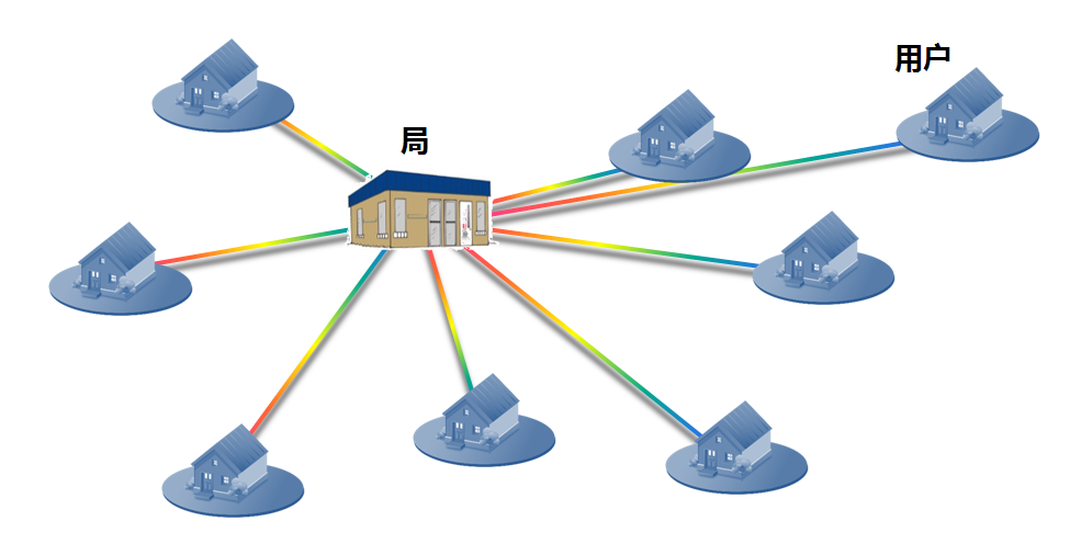
Figure 2: Point-to-Point Structure with One Fiber Optic Section
There are mainly two issues here: (1) The number of incoming fiber optic cables to the central office is large, but the number of incoming cables that a central office can accommodate is limited; (2) The distance for laying fiber optic cables during user installation is quite long, making it inconvenient for installation.
Due to these two limitations, the maximum number of users that such a central office can accommodate is only a few dozen, which obviously lacks application scenarios.
Two Fiber Optic Sections
To address the above issues, we make two improvements, as shown in Figure 3.
(1) The outgoing fiber optic cables from the central office use high-core-count cables, which are then split into multiple lower-core-count cables using fiber splicing boxes; however, if a single fiber optic cable has too many split points, it will affect the lifespan and transmission metrics of the cable.
(2) Set up a distribution box at locations where users are concentrated, serving as a boundary for engineering and installation; during user installation, only a short segment of fiber optic cable needs to be laid from the distribution box to the user.
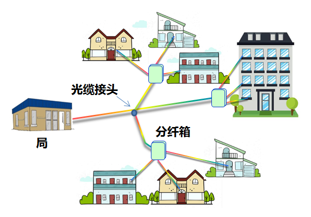
Figure 3: Network Structure with Two Fiber Optic Sections
Assuming a central office has 10 outgoing cables, each with 6 to 12 distribution boxes, and each distribution box serves 8 users, the estimated number of users served by one central office is between 480 and 960. At this point, the fiber optic route from the central office to the user has already changed into two sections: central office to distribution box and distribution box to user. Since the connection relationships at the fiber optic splicing points are fixed and have low loss, the splicing boxes are generally not considered the starting point of a section.
Compared to Figure 1, the number of users served by the central office in Figure 2 has increased several times, but the capacity is still too small; additionally, user development is dynamic, and if a new distribution box is needed at a location, the fiber optic cable needs to be laid again from the central office.
Three Fiber Optic Sections
From the comparison of Figures 3 and 2, it can be seen that from the perspective of reducing the number of outgoing fiber optic cables and facilitating installation, increasing the capacity of the central office can be achieved by adding split points on the fiber optic cables. The main split points for fiber optic cables are fiber optic junction boxes (hereinafter referred to as “fiber junctions”) and splicing boxes.
Through a fiber junction, a single fiber optic cable can be split into multiple cables, with the number of splits mainly limited by the installation conditions of the cables; the connection relationships between each cable are flexible, but this increases the loss of active connections and complicates core management.
The number of cables that can be split through a splicing box is relatively small, generally not exceeding 6 (1 to 5). There is usually some excess cable on both sides of the splicing box; if a splicing box splits too many cables, it can make the installation appear messy and unattractive, as shown in Figure 4; therefore, in general, the number of fibers split by a splicing box is controlled to within 4 (1 to 3).
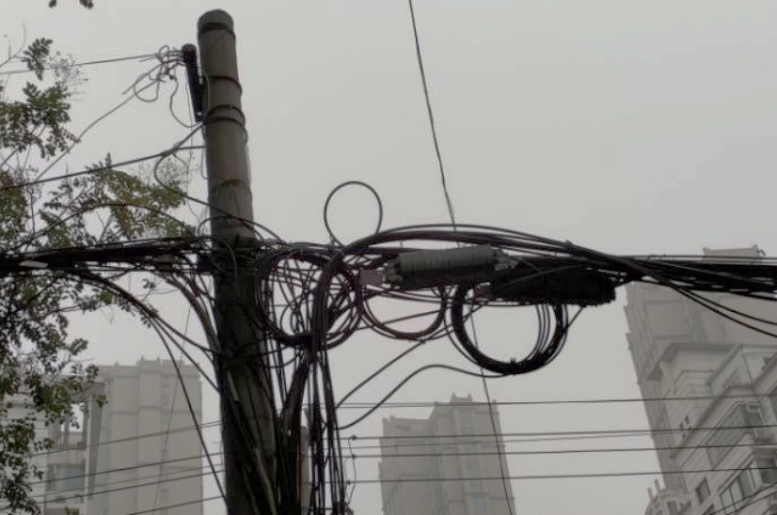
Figure 4: Current State of Fiber Cable Reserve on Both Sides of the Splicing Box
Based on Figure 3, after adding a fiber junction, the structure of the fiber optic network from the central office to the user is shown in Figure 5. Assuming one junction connects 10 incoming fiber optic cables, each having 6 to 12 distribution boxes, and each distribution box serving 8 users, the estimated number of users served by one junction is between 480 and 960.
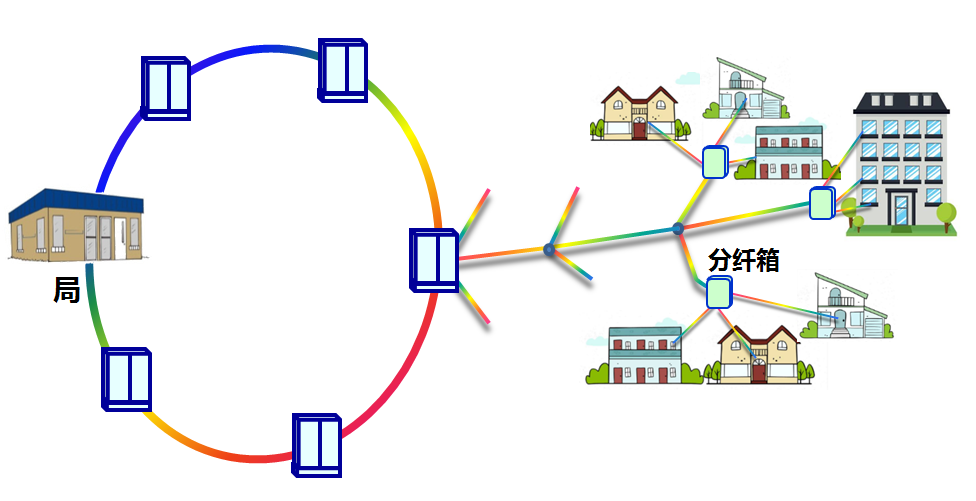
Figure 5: Network Structure with Three Fiber Optic Sections
So how many fiber junctions can a central office set up? Assuming a central office has 10 outgoing cables, with each cable connecting to an average of 3 junctions, it can set up 30 junctions. Thus, the capacity of one central office is approximately 14,400 to 28,800 users; such a large capacity can basically meet the needs of most scenarios.
Four Fiber Optic Sections
Engineering construction is always subject to construction conditions. For example, if the fiber optic network needs to cover a residential community, it is best to set up the junction within the community. However, during the construction of the main fiber optic cable for a central office, most community property management will not allow construction within their community; by the time the marketing department negotiates the construction conditions with a community, the main fiber optic construction will have already been completed.
The demands for engineering construction in urban residential communities, commercial buildings, and other clustered markets are uncertain, while the construction of main fiber optic cables must be completed within a certain time frame (generally within 2 to 3 months). To resolve this contradiction, during the construction of main fiber optic cables, the main fiber junction is set up at locations close to potential user groups, where laying fiber cables is convenient and installation conditions are available. When construction conditions are available in residential communities, commercial buildings, and other clustered markets, distribution fiber junctions are installed at these locations, and distribution cables are laid from the main fiber junction to the distribution fiber junction, as shown in Figure 6. Thus, the fiber optic route from the central office to the user is divided into the four sections shown in Figure 1: trunk section, distribution section, introduction section, and access section.
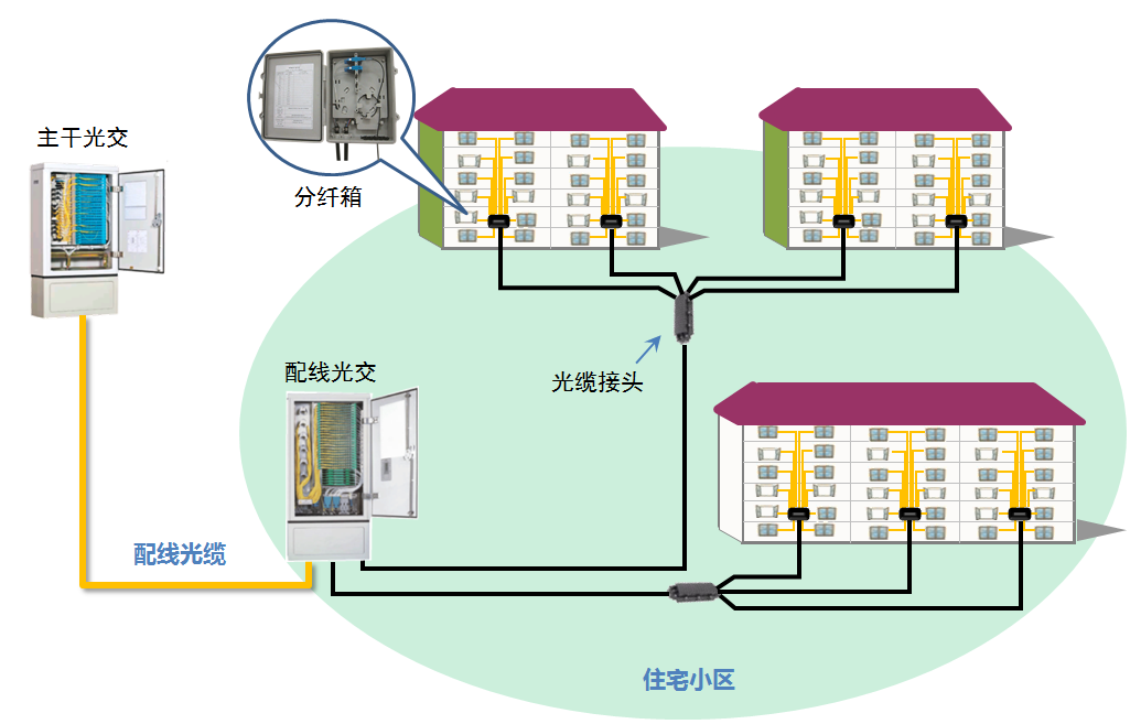
Figure 6: Fiber Network from Main Fiber Junction to User
The setting of distribution fiber junctions can further increase the number of users that the central office can cover. So how many distribution fiber junctions can a main fiber junction support? It is believed that 5 to 10 is appropriate; if it only supports 2 to 3 distribution fiber junctions, it might be better to change the main fiber junction to a splicing box.
Conclusion
Currently, the fiber optic route from the central office to the user mainly consists of the four-section structure shown in Figure 1, but we should also recognize that too many sections of fiber can degrade the quality of the fiber link and complicate the connection relationships of the fiber link.
The separate installation of main fiber junctions and distribution fiber junctions is mainly to resolve the timing issues between the construction of the main fiber optic cable and the introduction fiber optic cable. In scenarios where construction timing is not affected, such as when the coverage area of a central office belongs to the same town or residential area, there is little significance in separately setting up the main and distribution fiber junctions.