Introduction:
In embedded system development, Real-Time Operating Systems (RTOS) play a crucial role in effectively managing the execution of multiple tasks, enhancing system concurrency and response speed. FreeRTOS, as a widely used open-source RTOS, has core design concepts and implementation mechanisms that are worth in-depth study and learning. To better understand how an RTOS works, I decided to mimic the core code of FreeRTOS and implement a simplified version of an RTOS. The main differences between this simplified RTOS and the standard FreeRTOS are:
-
No priority/suspension: All tasks have the same priority and use a simple round-robin scheduling strategy.
-
Only supports time-slice round-robin scheduling: Does not support other complex scheduling algorithms, such as priority preemptive scheduling.
This article will detail the implementation process of this simplified RTOS, from task creation, scheduler design to exception handling, gradually analyzing its core code and design ideas. The next article (the second half) will cover some driver functions for the peripherals of this operating system.
Next, I will write out a simple FreeRTOS step by step.Table of Contents:
1. Task Breakdown
-
OS Initialization and Interrupt Management
-
Task Creation and Startup
-
Task Round-Robin Scheduling
-
Exception Handling
2. Detailed Analysis of the Implementation Ideas of the Simple OS
(1) OS Initialization and Interrupt Management
-
Vector Table Initialization (start.s)
Reset Handler (Reset_Handler)
Exception Handling Interrupt Design
(2) Task Creation and Startup
-
Task Creation (task.c)
-
Task Startup (start.s)
(3) Task Round-Robin Scheduling
-
SysTick Interrupt Service Function (SysTick_Handler_asm)
2. Scheduler Implementation (systick.c)
(4) Exception Handling
-
HardFault_Handler
-
UsageFault_Handler
-
SVC_Handler
-
UsageFaultInit
3. Implementation of the OS Main Function
-
Stack Space Definition and Alignment (stack_a-d)
-
Task Function Definition
Task Creation and Startup
4. Summary of the ArticleThis article implements a simplified version of an RTOS based on time-slice round-robin scheduling, completing hardware initialization and interrupt vector table setup through start.s, initializing task stacks with create_task and simulating register states, and using SysTick interrupts to trigger task switching, achieving concurrent execution of multiple tasks.1. Task BreakdownBased on the previous articles and the two differences mentioned above, we can plan out several steps to achieve our goal:1. OS Initialization and Interrupt Management2. Task Creation and Startup3. Task Round-Robin Scheduling4. Exception HandlingThese four tasks are interlinked and implementing them will help us achieve our goal. Below, I will analyze these four steps in detail with my code.2. Detailed Analysis of the Implementation Ideas of the Simple OS1. OS Initialization and Interrupt ManagementI set up a start.s file as theprocessor startup file, written in assembly language, responsible forinitializing the hardware environment & setting the interrupt vector table andbooting the system into the main C program (such as <span><span>main()</span></span>).(1) Vector Table Initialization (start.s)
; Vector Table Mapped to Address 0 at Reset AREA RESET, DATA, READONLY EXPORT __Vectors EXPORT StartTask_asm IMPORT HardFault_Handler IMPORT UsageFault_Handler IMPORT SVC_Handler IMPORT SysTick_Handler__Vectors DCD 0 DCD Reset_Handler ; Reset Handler DCD 0 ; NMI Handler DCD HardFault_Handler ; Hard Fault Handler DCD 0 ; MPU Fault Handler DCD 0 ; Bus Fault Handler DCD UsageFault_Handler_asm ; Usage Fault Handler DCD 0 ; Reserved DCD 0 ; Reserved DCD 0 ; Reserved DCD 0 ; Reserved DCD SVC_Handler ; SVCall Handler DCD 0 ; Debug Monitor Handler DCD 0 ; Reserved DCD 0 ; PendSV Handler DCD SysTick_Handler_asm ; SysTick Handler-
Defines the vector table mapped to address 0 at reset
-
Each DCD entry corresponds to the address of an exception handler
-
Includes important interrupt vectors such as reset, hard fault, system call (SVC), SysTick, etc.
In the last two lines, we can see the previously mentioned PendSV and SysTick interrupts. In this task, since only time-slice round-robin scheduling is supported, there is no need for a separate PendSV. We directly implement task scheduling inSysTick.
(2) Reset Handler (start.s)
Reset_Handler PROC LDR SP, =(0x20000000+0x10000) ; Initialize stack pointer to the end of RAM BL SystemInit ; Initialize system clock, etc. BL uart_init ; Initialize UART BL UsageFaultInit ; Initialize usage fault handling BL SysTickInit ; Initialize system timer BL LedInit ; Initialize LED BLX mymain ; Jump to main program ENDPThis interrupt is triggered at system startup to initialize some hardware requirements
-
It is the first code executed after system startup
-
Initializes the stack pointer, hardware peripherals, and system components
-
Finally jumps to the C language main function
Exception Handling Interrupt Design (start.s)
UsageFault_Handler_asm PROCMOV R0, SPB UsageFault_HandlerENDPThis interrupt is called during system exceptions (usage faults, not hardware), and it will pass the stack pointer to the handling function
-
Passes the current stack pointer to the C language handling function
-
Used for debugging and error diagnosis
Its handling function (in the exception.c exception handling module)
void UsageFault_Handler(unsigned int *stack){ SCB_Type * SCB = (SCB_Type *)SCB_BASE_ADDR;puts("UsageFault_Handler\n\r");put_s_hex("R0 = ", stack[0]);put_s_hex("R1 = ", stack[1]);put_s_hex("R2 = ", stack[2]);put_s_hex("R3 = ", stack[3]);put_s_hex("R12 = ", stack[4]);put_s_hex("LR = ", stack[5]);put_s_hex("PC = ", stack[6]);put_s_hex("xPSR= ", stack[7]);/* 1. clear usage fault */ SCB->CFSR = SCB->CFSR;/* 2. set return address in sp, point to next instruction */ stack[6] += 4;}This function will find the location of the error stack, output the values of all registers for user judgment, and move the stack pointer to execute the next instruction.2. Task Creation and StartupThis step mainly relies on a large number of task operation functions in the task module and the StartTask_asm task startup function in start.s.(1) Task Creation (task.c)
void create_task(task_function f, void *param, char *stack, int stack_len){int* top=(int*)(stack+stack_len); top-=16;//The following are R4-11 (software part) top[0]=0; top[1]=0; top[2]=0; top[3]=0; top[4]=0; top[5]=0; top[6]=0; top[7]=0; top[9]=0;//R0 saves entry parameters top[8]=(int) param;//R1,2,3,12 top[10]=0; top[11]=0; top[12]=0;//lr currently has no content top[13]=0; top[14]=(int)f;//14 is the pointer to the execution function, executed with r0 parameters top[15]=(1<<24);//Instruction set setting Task_stack_addr[task_count++] = (int)top;//Address of the stack}Fakes the stack saved by the task, allocates a block of memory from the stack (according to user requirements malloc, at least 16), fills in the values of 16 registers in order, so that it can be restored to the CPU and run normally.
This table explains the role of each register, the order of saving, and the saving method
Register Save List (Stack Offset Order)
|
Stack Offset ( |
Register |
Saving Method |
Usage Description |
|---|---|---|---|
|
|
R4 |
Manually initialized (=0) |
Caller-saved register, meaningless when the task runs for the first time, initialized to 0. |
|
|
R5 |
Manually initialized (=0) |
Same as above. |
|
|
R6 |
Manually initialized (=0) |
Same as above. |
|
|
R7 |
Manually initialized (=0) |
Same as above. |
|
|
R8 |
Manually initialized (=0) |
Same as above. |
|
|
R9 |
Manually initialized (=0) |
Same as above. |
|
|
R10 |
Manually initialized (=0) |
Same as above. |
|
|
R11 |
Manually initialized (=0) |
Same as above. |
|
|
R0 |
Set to |
Task parameter passing stores |
|
|
R12 |
Manually initialized (=0) |
Temporary register, meaningless when the task runs for the first time. |
|
|
R1 |
Manually initialized (=0) |
Temporary register, initialized to 0. |
|
|
R2 |
Manually initialized (=0) |
Temporary register, initialized to 0. |
|
|
R3 |
Manually initialized (=0) |
Temporary register, initialized to 0. |
|
|
LR |
Manually initialized (=0) |
Link Register, the task does not return, so set to 0. |
|
|
PC |
Set to |
Program Counter points to the task function |
|
|
xPSR |
Set to |
Program Status Register, Bit 24=1 indicates Thumb mode (required for Cortex-M). |
(2) Start the Created Task (start.c)
StartTask_asm PROC; Task starter: gives the stack position and return method to start the task in the stack ;r0: stack address of task ;r1: lr (method of executing start/return task) LDMIA R0!, {R4-R11} ;other r's are stored by hardware MSR MSP, R0 ;Msp is the point of task stack BX R1 ;return to this task(lr: return way ;msp: return place) ENDP-
Restores registers R4-11 from the provided stack address (others are automatically restored)
-
Finds the stack pointer of this task and starts the task code contained in this stack
Each task startup method is quite similar.3. Task Round-Robin SchedulingMy operating system can only perform task switching based on time-slice round-robin, so the switching function is closely tied to theSysTick interrupt.
static int Task_stack_addr[32];I defined an array containing the positions of all task stacks, corresponding to the task list in the previous source code, to facilitate quick calls to each task.(1) SysTick Interrupt Service Function (triggered on time-slice overflow)
SysTick_Handler_asm PROC STMDB sp!, {r4-r11} STMDB sp!, {lr} ;save rg+lr of this task MOV R0,LR ADD R1, SP, #4 ; stack top (r1+4 because we saved lr) BL SysTick_Handler ;c function to change LDMIA sp!, { r0 } LDMIA sp!, { r4 - r11 } ;return rg+lr of this task BX R0 ;run by lr(in r0) and sp ENDP ENDSave the context
STMDB sp!, {r4-r11} STMDB sp!, {lr}Saves registers R4-R11 to the stack, while others are automatically saved.
Saves lr (return method) for preparation to return.
Calls the switching function with two parameters, lr and sp
MOV R0,LR ADD R1, SP, #4 ; stack top (r1+4 because we saved lr) BL SysTick_Handler ;c function to changeSwitching function (systick.c)
void SysTick_Handler(int lr_bak,int old_sp){int stack;int old_task;int new_task; SCB_Type * SCB = (SCB_Type *)SCB_BASE_ADDR; SCB->ICSR |= SCB_ICSR_PENDSTCLR_Msk; //clear interruptif(!is_task_running())//if no task created {return; //return will directly return to source task}if(cur_task==-1)//whether tasks have been started (there are tasks that have not been started) { cur_task=0; stack=get_stack(cur_task);//get task addressStartTask_asm(stack, lr_bak);//start taskreturn;}else { old_task=cur_task; new_task=get_next_task();if(old_task!=new_task) {//first save old task (we need to save to the return table, note: the address in the return table needs to be updated continuously)set_task_stack(old_task, old_sp);//switch task stack = get_stack(new_task); cur_task=new_task;//update task pointerStartTask_asm(stack,lr_bak); } }}First clear the interrupt flag, then store the old stack pointer in the linked list, extract the next stack pointer from the linked list, and execute the next task based on lr.
In addition to these core functions, there are many other task handling functions
int cur_task=-1;//Currently running program numberint old_task = -1; // Initialize to invalid valueint task_count=0;// Program countint task_running = 0;//running stateint is_task_running(void)//get running state{return task_running;}int get_stack(int cur_task)//get task address{return Task_stack_addr[cur_task];}int get_next_task(void)//increment to process the next task{int index = cur_task; index++;if (index >= task_count) index = 0;return index;}void set_task_stack(int task, int sp)//save for{ Task_stack_addr[task] = sp;}void start_task(void){ task_running = 1;while (1);}These functions assist the core switching function above. After initializing a task, we just need to use task_running to free up the timer. SysTick will allow all tasks to run.
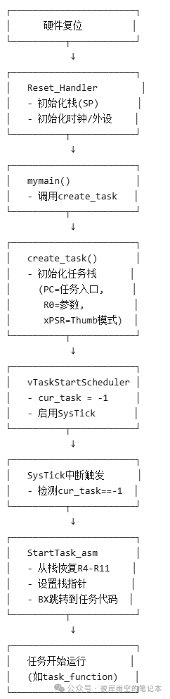
This image illustrates how tasks begin to run, with subsequent tasks being scheduled by the SysTick scheduler.
4. Exception Handling (exception.c)
#include "uart.h"#include "exception.h"void HardFault_Handler(void){puts("HardFault_Handler\n\r");while (1);}void UsageFault_Handler(unsigned int *stack){ SCB_Type * SCB = (SCB_Type *)SCB_BASE_ADDR;puts("UsageFault_Handler\n\r");put_s_hex("R0 = ", stack[0]);put_s_hex("R1 = ", stack[1]);put_s_hex("R2 = ", stack[2]);put_s_hex("R3 = ", stack[3]);put_s_hex("R12 = ", stack[4]);put_s_hex("LR = ", stack[5]);put_s_hex("PC = ", stack[6]);put_s_hex("xPSR= ", stack[7]);/* 1. clear usage fault */ SCB->CFSR = SCB->CFSR;/* 2. set return address in sp, point to next instruction */ stack[6] += 4;}void SVC_Handler(void){puts("SVC_Handler\n\r");}void UsageFaultInit(void){ SCB_Type * SCB = (SCB_Type *)SCB_BASE_ADDR; SCB->SHCSR |= (SCB_SHCSR_USGFAULTENA_Msk);}This program is for ARM Cortex-M processors exception handling code, mainly handling HardFault (hard error), UsageFault (usage error) and SVC (system call) three types of exceptions.
(1) HardFault_Handler(void)
Triggered when a hardware error occurs, including illegal memory access (such as accessing unmapped addresses), stack overflow (SP pointing to illegal areas), and other serious hardware errors, prints error information, and enters an infinite loop (requires external reset).
(2) UsageFault_Handler
This usage fault was mentioned earlier, generally triggered by unaligned memory access (such as non-4-byte aligned <span><span>int</span></span> read/write), executing undefined instructions (such as illegal opcodes), and division by zero errors (requires enabling the <span><span>DIV_0_TRP</span></span> bit):
-
Print register status:
Accesses the registers pushed onto the stack during the exception (
<span><span>R0-R3, R12, LR, PC, xPSR</span></span>). -
Clear error flags:
Writes to
<span><span>SCB->CFSR</span></span>(Configurable Fault Status Register) to clear the error status. -
Skip erroneous instructions:
Modifies the
<span><span>PC</span></span>in the stack (<span><span>stack[6]</span></span>), pointing it to the next instruction (<span><span>+4</span></span>applies to most Thumb instructions).
(3) SVC_Handler
void SVC_Handler (void) { puts("SVC_Handler\n\r"); }Only prints debugging information; in actual use, the SVC number needs to be parsed and the corresponding operation executed.(4) UsageFaultInitEnables the UsageFault exception (<span>SCB->SHCSR</span> (System Handler Control and State Register) USGFAULTENA bit)The above four parts are the core code of the simple operating system. Now, we only need a main function to create and run tasks.3. OS Main Function
#include "uart.h"#include "string.h"#include "task.h"static char stack_a[1024] __attribute__ ((aligned (4)));;static char stack_b[1024] __attribute__ ((aligned (4)));;static char stack_c[1024] __attribute__ ((aligned (4)));;static char stack_d[1024] __attribute__ ((aligned (4)));;void task_a(void *param){char c = 'e';while (1) {putchar(c);}}void task_b(void *param){char c=(char)param;while(1) {putchar(c);}}void task_c(void *param){char c=(char)param;while(1) {putchar(c);}}void task_d(void *param){int i;int sum = 0;for (i = 0; i <= 100; i++) sum += i;while (1) {put_s_hex("sum = ", sum);}}int mymain(){create_task(task_a, 'b', stack_a, 1024);create_task(task_b, 'a', stack_b, 1024);create_task(task_c, 'c', stack_c, 1024);create_task(task_d, '0', stack_d, 1024);start_task();return 0;}(1) Request 1024 size stack space aligned to four bytes
staticchar stack_a[1024] __attribute__ ((aligned (4)));;staticchar stack_b[1024] __attribute__ ((aligned (4)));;staticchar stack_c[1024] __attribute__ ((aligned (4)));;staticchar stack_d[1024] __attribute__ ((aligned (4)));;(2) Create task processing functions
voidtask_a(void *param){char c = 'e';while (1){putchar(c);}}(3) Create tasks for the stack and task processing functions
create_task(task_a, 'b', stack_a, 1024);(4) Hand over time to the scheduler
start_task();In summary, the main function, as the entry point of the program, is responsible for initializing the multi-task environment and starting the task scheduler. The core logic is:
-
Create 4 tasks: Allocate stack space and set task entry functions.
-
Start the scheduler: Trigger task switching through
<span><span>start_task()</span></span>to enable concurrent execution of tasks.
4. Summary of the Article
This article provides a detailed overview of the implementation process of a simplified RTOS, from OS initialization, task creation and startup, task round-robin scheduling to exception handling, gradually analyzing the design ideas of the core code. Although this simplified RTOS has basic functionality, it covers the core mechanisms of an RTOS, such as task scheduling, context switching, and exception handling. The second half of this article will initialize some external drivers corresponding to this operating system.