Virtual simulation experiments are an important direction in the reform of physics experimental teaching. Since their official use in university physics laboratory courses in the 1990s, they have greatly promoted the development of physics laboratory teaching across the country. However, as the reform of experimental teaching deepens and the demand for university physics laboratory teaching increases across various majors, earlier simulations, which primarily served as a pre-experiment tool with high visual fidelity but low physical connotation fidelity, can no longer fully meet teaching requirements. Quantitative simulations based on accurate physical models are gradually becoming the mainstay of simulation experiments. The National Physics Experiment Teaching Demonstration Center at Sun Yat-sen University has set up several experimental modules that combine virtual and real experiments, including “experimental simulation experiments” in the branches of mechanics and thermodynamics within the basic physics laboratory course. This approach aims to integrate theoretical physics, experimental physics, and computational physics, allowing students to engage in experimental work using research and engineering design thinking from their early years. This virtual-real combined teaching model can effectively enhance students’ innovation abilities and knowledge application skills, achieving good teaching results.
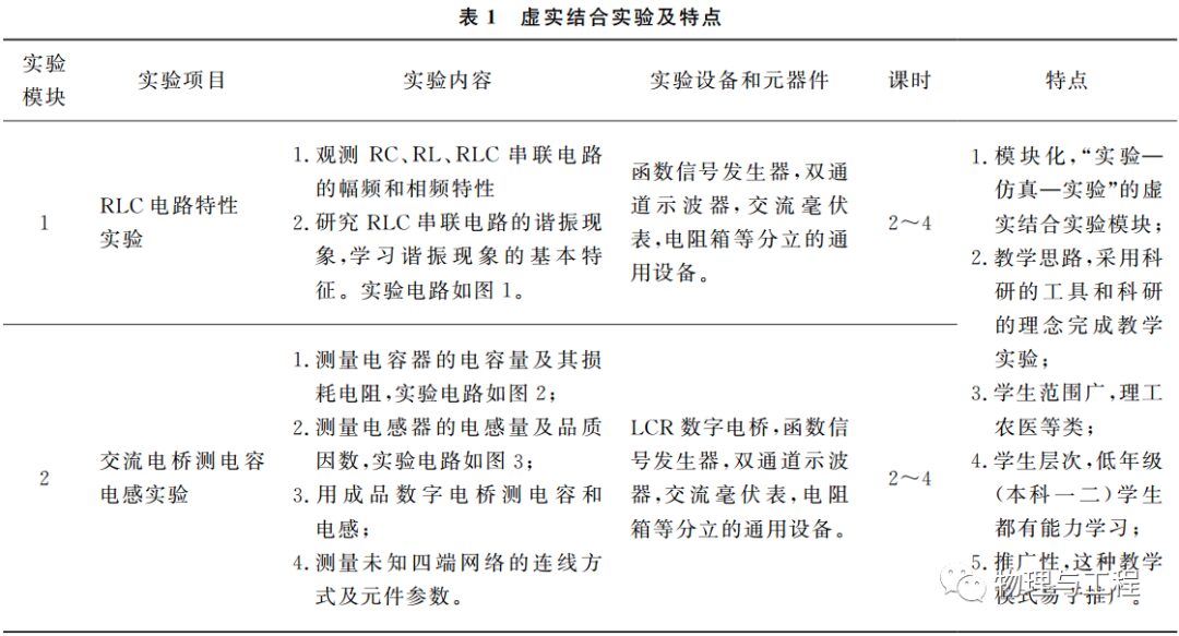
This article will detail the virtual-real combined electric experiment module. This module integrates teaching content such as RLC circuit characteristics, AC bridge measurement of capacitance and inductance, and chaotic circuit experiments on the NI hardware platform, using widely used software like LabVIEW and Multisim. The aim is to enable students to engage early with Multisim circuit simulation software and LabVIEW programming technology, combining physical teaching to include rich content within limited teaching hours, enhancing the practicality and challenge of the teaching process. The experiments are divided into three parts: (1) Conducting physical experiments to complete RLC circuit characteristics or AC bridge measurement of capacitance and inductance to obtain experimental data; (2) Using Multisim simulation software to verify the results of the above experiments, adjusting simulation parameters to make the simulation results as consistent as possible with the experimental results, while also conducting predictive simulations of chaotic circuit experiments to predict experimental results; (3) Using LabVIEW programming to control the NI_myDAQ data acquisition device to complete the chaotic circuit experiment with physical components, comparing experimental results with simulation results, evaluating similarities and differences, and discussing the reasons. This process of “experimental simulation experiments” cycles multiple times, continuously improving experimental and simulation models, similar to the research process, to promote the development of students’ abilities. Mathematical software such as MatLab and Mathematica are also excellent simulation tools, but in lower-grade experimental teaching, unless there are other programming courses to accompany it, and students are required to prepare simulation programs before class or provided by teachers, it is difficult to complete the construction and simulation of physical models in class. Therefore, commercially available software used in research and engineering design is chosen for simulation. The characteristics of virtual-real combined experiments are shown in Table 1.


1 RLC Circuit Characteristics or AC Bridge Physical Experiment
The first part of the virtual-real combined experiment module is to complete a basic physical experiment, either the RLC series circuit AC steady-state characteristics experiment or the AC bridge measurement of capacitance and inductance experiment, both of which have similar difficulty levels, allowing the selection of either during teaching. Using traditional teaching methods, students can use discrete general-purpose devices such as function signal generators, dual-channel oscilloscopes, AC millivoltmeters, and resistance boxes to build experimental circuits themselves and complete the experiment, meeting the basic requirements of university physics laboratory teaching.
1.1 RLC Series Circuit AC Steady-State Characteristics Experiment
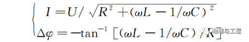
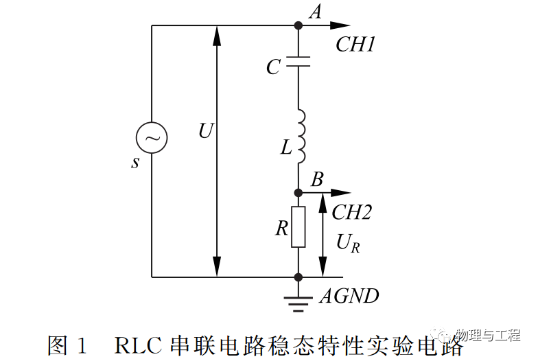
The experimental circuit is shown in Figure 1, where the resistance R=512.01Ω, the inductance L=2.28mH, and the capacitance C=100.80nF. The digital function signal generator S outputs a sine signal to the RLC series circuit, and the signal input ends of the digital oscilloscope (CH1 and CH2) are connected to points A and B in Figure 1, simultaneously observing the total voltage U across the series circuit and the voltage UR across the resistor. Based on I=URR and the phase difference Δφ of the two waveforms, analyze the amplitude-frequency characteristics and phase-frequency characteristics of the circuit. According to the steady-state characteristics of the AC circuit, the theoretical values of I and Δφ for the RLC series circuit are
(1)
This part emphasizes the introduction of the physical description of complex impedance in alternating circuits, allowing students to discover that the vector diagram method is an effective way to solve alternating circuit analysis. This lays the groundwork for subsequent simulation experiments.
1.2 AC Bridge Measurement of Capacitance and Inductance Experiment
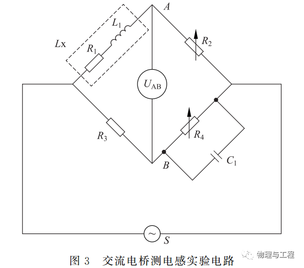
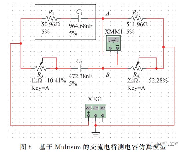
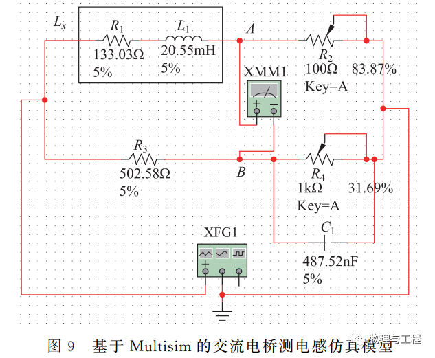
The AC bridge and DC bridge are important teaching content in university physics experiments and are core circuits for many precision measurements and sensors. The AC bridge can measure capacitance and inductance values with high precision and is the basis of impedance analyzers. For physics majors with high experimental requirements, this content can be selected. The circuit for measuring capacitance with the AC bridge is shown in Figure 2, while the circuit for measuring inductance is shown in Figure 3.
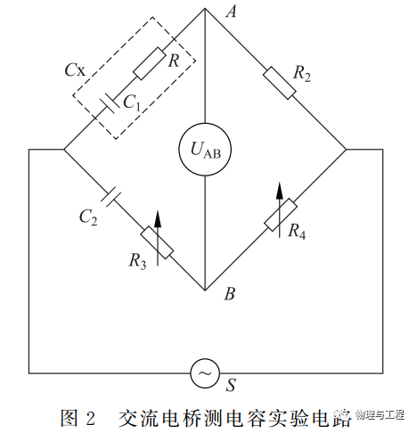
In Figure 2, the measured physical capacitor CX is composed of a pure capacitor C1 and a loss resistance R1 in series. The resistance values of R1 and R2 measured by a 5-3/4 digit digital multimeter are R1=50.96Ω and R2=511.96Ω, while R3 is a 1kΩ potentiometer and R4 is a 2kΩ potentiometer. Using a commercial RLC measuring instrument, C1=964.68nF and loss D1=0.306 are measured; C2=472.38nF. During the experiment, the function signal generator S outputs a sine signal with a frequency f=1kHz and a peak-to-peak value VPP=5V, and the AC millivoltmeter measures the voltage UAB between points A and B. Adjusting R3 and R4 to minimize UAB balances the bridge. In the absence of shielding, UAB can be adjusted to below 5mV, at which point R3=100.82Ω and R4=1049.2Ω are measured. Based on the balance condition of the AC bridge, the following can be obtained:

(2)
Compared to the measurement results of commercial measuring instruments, the relative errors are 3.48%, 0.35%, and 2.21%, respectively.
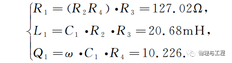
In Figure 3, the measured physical inductor LX is composed of a pure inductor L1 and resistance R1 in series. The resistance values of R1 and R3 measured by a 5-3/4 digit digital multimeter are R1=133.03Ω and R3=502.58Ω, while R2 is a 100Ω potentiometer and R4 is a 1kΩ potentiometer. Using a commercial RLC measuring instrument, L1=20.55mH and quality factor Q1=9.86 are measured; C1=487.52nF. During the experiment, the function signal generator S outputs a sine signal with a frequency f=10kHz and a peak-to-peak value VPP=5V, and the AC millivoltmeter measures the voltage UAB between points A and B. Adjusting R2 and R4 balances the bridge. In the absence of shielding, UAB can be adjusted to below 5mV, at which point R2=84.38Ω and R4=333.86Ω are measured. Based on the balance condition of the AC bridge, the following can be obtained:

Compared to the measurement results of commercial measuring instruments, the relative errors are 4.52%, 0.62%, and 3.72%, respectively.
The bridge is a basic method for college students to conduct precise measurements in electricity. Through physical measurements, students can understand the concept of differential and design different impedance characteristic bridges to solve the measurement problems of alternating impedances. The experiments with the AC bridge involve the measurement of resonant frequencies, and some high-frequency signal measurements are limited by instruments. An effective way to address this challenge is simulation. Building on physical experiments, broadening cognitive scope with intuitive understanding is an indispensable advantage of simulation.
2 Multisim Circuit Simulation Experiment
This part of the experiment is divided into two stages: the first is to conduct verification simulations of the above experiments, and the second is to perform predictive simulations for the subsequent chaotic circuit experiments. According to the teaching rhythm, teachers can choose to conduct physical experiments first and simulations afterwards; or they can start with simulations to understand the overall characteristics and then conduct physical experiments, analyzing the sources of uncertainty in the physical experiments. This unit of experiments transitions from the study of basic electrical parameters to the analysis of the overall characteristics of specific circuits, linking the two, and the process of “experimental verification and predictive experiments” resembles the thinking process of research.
2.1 RLC Circuit and AC Bridge Verification Simulation
(1) RLC Circuit Verification Simulation
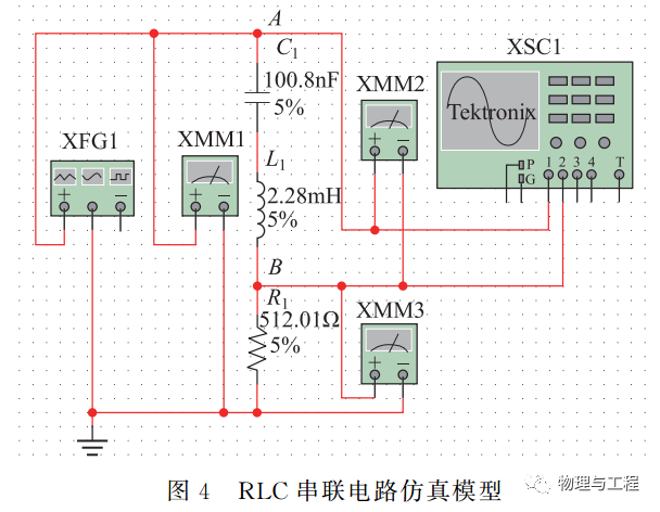
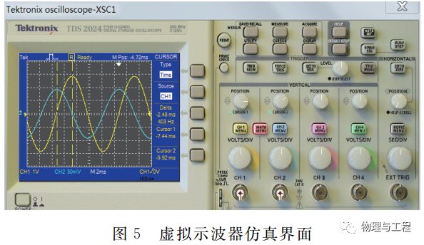
In Multisim, the simulation model of the RLC series circuit is shown in Figure 4. Here, XFG1 is the virtual function signal generator, XMM1 to 3 are three virtual digital multimeters, and XSC1 is the virtual oscilloscope. The simulation circuit, component parameters, and AC signal parameters are consistent with the physical experiments. Use XMM1 to measure the ground voltage U at point A, and XMM3 to measure the ground voltage UR at point B, characterizing the amplitude-frequency characteristics with I=URR. The simulation interface of the virtual oscilloscope is shown in Figure 5, which is completely consistent with physical instruments, allowing the phase difference of the two waveforms to be determined using the cursor measurement method based on the waveforms.
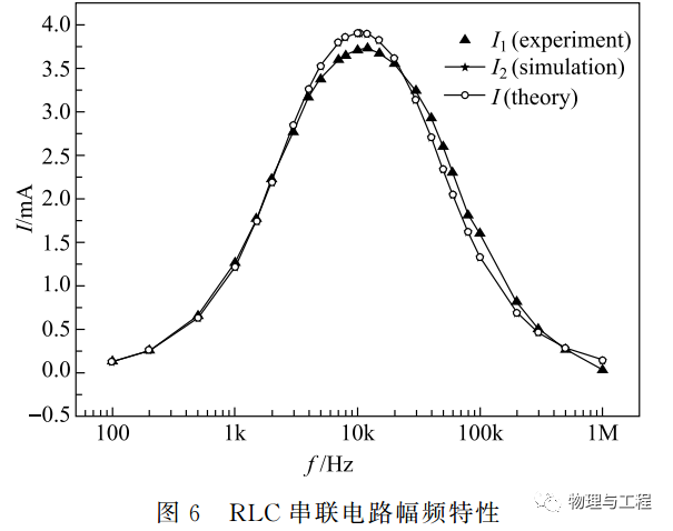
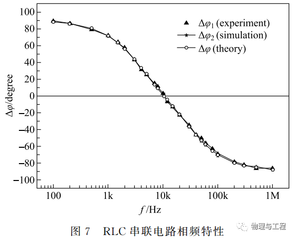
The results of the virtual-real combined experiments for amplitude-frequency and phase-frequency characteristics are shown in Figures 6 and 7, respectively. In Figure 6, I1 is the measurement result from the physical experiment, I2 is the result from the Multisim simulation, and I is the theoretical calculation result; the three align very well. In Figure 7, Δφ1 is the measurement result from the physical experiment, Δφ2 is the result from the Multisim simulation, and Δφ is the theoretical calculation result; the three also align very well. The theoretical, experimental, and simulation methods were all applied in this experiment.
This part of the experiment is conducted by first-year university students, requiring them to implement logical link organization, analysis, and systematic thinking capability construction from physical experiments to outputs, effectively enhancing students’ comprehensive abilities.
(2) AC Bridge Verification Simulation
In Multisim, the simulation model for measuring capacitance with the AC bridge is shown in Figure 8, and the simulation model for measuring inductance is shown in Figure 9, where XMM1 is the virtual digital multimeter, XFG1 is the virtual function signal generator, and the simulation component parameters are consistent with the physical experiments. In the simulation of Figure 8, when adjusting to balance the bridge, R3=104.1Ω and R4=1045.6Ω, substituting into equation (2) yields R1=50.97Ω, C1=964.76nF, and D1=0.309. Compared to the measurement results of commercial measuring instruments, the relative errors are 0.005%, 0.009%, and 0.969%, respectively. In the simulation of Figure 9, when adjusting to balance the bridge, R2=83.87Ω and R4=316.9Ω, substituting into equation (3) yields R1=133.01Ω, L1=20.549mH, and Q1=9.707. Compared to the measurement results of commercial measuring instruments, the relative errors are 0.02%, 0.008%, and 1.55%. The simulation results for the capacitance and inductance measurement circuits align very well with the experimental results.
The adjustments of various parameters in this experiment can be set according to the specific conditions of the experimental components. Generally speaking, students entering the laboratory have not yet established the concept of precision and overall performance. This part of the experiment requires teachers to inspire students to build reasonable simulation systems, so that simulations can be targeted and complementary to physical experiments.
2.2 Predictive Simulation of Chaotic Circuit Experiment
The chaotic circuit is intended to be implemented using the “Chua’s circuit”. Due to the sensitivity of the phenomena in physical experiments to circuit parameters, the adjustment precision of the resistance in the oscillation state needs to be below 1Ω, and it is also affected by contact resistance, stray capacitance, and other factors. If students conduct experiments directly, due to inexperience, they may adjust the resistance too quickly and miss the oscillation point, thus failing to observe chaotic phenomena. Simulation experiments are not affected by the aforementioned interference factors. If the parameter range of the circuit components can be determined through simulation experiments, adjustments can be made accordingly during physical experiments, significantly increasing the success rate of the experiments.
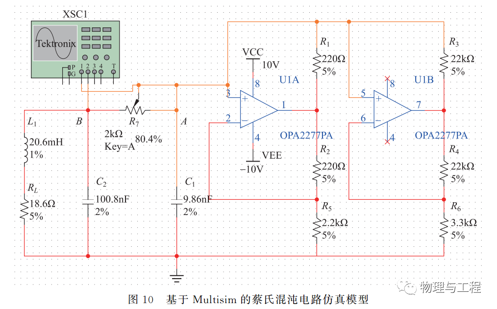
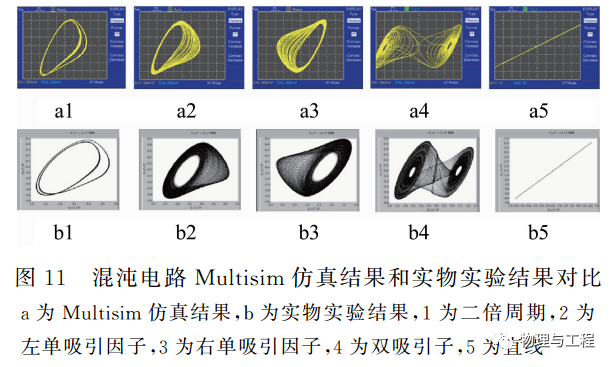
In Multisim, the simulation model of Chua’s circuit is shown in Figure 10, where U1 is the OPA2277PA operational amplifier, and XSC is the oscilloscope, with two channels measuring the waveforms at points A and B, displayed in X-Y mode to show chaotic phenomena. The component parameters are shown in the figure, and careful adjustments to the resistance value of R7 can reveal various chaotic phenomena, as shown in a1~a5 of Figure 11. When R7 is between 1740~1760Ω, a double-period graph of a1 is obtained; when between 1665~1728Ω, a single attractor graph of a2 or a3 is obtained; when between 1434~1664Ω, a double attractor graph of a4 is obtained; and when 0Ω, a linear graph of a5 is obtained. From the simulation, it can be seen that the single attractor graph of a2 or a3 is the difficulty in experimental adjustments.
3 Chaotic Circuit Physical Experiment
The physical experiment requires students to use discrete components to connect and complete the circuit on a breadboard, with the circuit and component parameters as shown in Figure 10. However, the virtual oscilloscope is replaced with a dual-channel oscilloscope designed using NI_myDAQ, with CH0 and CH1 measuring the waveforms at points A and B, respectively. The dual-channel oscilloscope uses the NI_myDAQ data acquisition device, controlled by LabVIEW programming, with its front panel shown in Figure 12. In Figure 10, R7 uses a 10-turn precision adjustable potentiometer. Referring to the simulation results, by carefully adjusting the resistance value of R7, various chaotic phenomena observed in the simulation can be seen using the oscilloscope, as shown in b1 to b5 of Figure 11. When R7 is between 1750~1758Ω, a double-period graph of b1 is obtained; when between 1685~1731Ω, a single attractor graph of b2 or b3 is obtained; when between 1453~1684Ω, a double attractor graph of b4 is obtained; and when 0Ω, a linear graph of b5 is obtained. As seen in Figure 11, the results of the physical experiment align very well with the simulation results. Furthermore, mathematical software such as MatLab or Mathematica can be used to calculate chaotic phenomena based on the theoretical formulas of Chua’s chaotic circuit, comparing the results of physical experiments and simulations.
Chaos is a very important nonlinear initial value-dependent motion pattern encountered during the university physics stage. The parameters affecting chaos are included in this part of the experiment, allowing students to thoroughly understand the physical mechanisms of chaotic phenomena through building simulation circuits themselves, and further study the physical essence of chaos, establishing a good physical image for future studies.
4 Conclusion
In summary, the virtual-real combined electric experiment can complete the measurement of basic electrical quantities and the simple dependency relationships between electrical quantities, as well as further understanding the generation and regulation of nonlinear electrical phenomena such as chaos within 4 to 12 teaching hours. The experiment involves industry-standard technologies such as Multisim circuit simulation, NI_myDAQ data acquisition, and LabVIEW programming, while also covering rich physical concepts and laws such as RLC circuits, AC bridges, and chaotic circuits. The teaching process of “experiment – verification simulation – predictive simulation – experiment” compares the results of theory, experiment, and simulation, guiding lower-grade students to complete teaching experiments using research and engineering design thinking methods, providing a cultivation platform to effectively enhance students’ problem-solving abilities, utilize foundational knowledge, integrate applications, and innovate; laying a good foundation for students’ subsequent research training and experimental competitions.
References
[1] Huo Jianqing. Thoughts and practices on the experimental teaching mode applying information technology to cultivate innovative talents. Physics and Engineering, 2013, 23(6): 26-29, 37.
[2] Wang Xiaopu, Yang Bo, Yin Zhiming, et al. Computer simulation systems in experimental teaching. College Physics, 1997, 16(5): 21-23.
[3] Le Yongkang, Gong Xinga, Su Weifeng, et al. Physics experiment teaching integrated with virtual-reality technology. Physics Experimentation, 2017, 37(01): 39-43.
[4] Li Weiyang, Wang Yewu, Chen Shuiqiao, et al. Teaching design and practice of virtual-real combination in basic physics experiments. Physics and Engineering, 2018, 28(S1): 151-156 + 161.
[5] Wang Xin, Yang Hujiang. Research and practice of physics experiment teaching based on virtual-real combination. Physics Experimentation, 2015, 35(10): 15-18 + 22.
[6] Shen Han. Basic Physics Experiments. Beijing: Science Press, 2015.
[7] Shen Han. Establishment of physics experimental teaching system using international general-purpose instruments. Physics Experimentation, 2017, 37(8): 29.
[8] Ministry of Education of the People’s Republic of China. Basic requirements for teaching university physics laboratory courses for science and engineering majors (2010 edition). Beijing: Higher Education Press, 2011.
[9] Wang Kaiyu, Lu Cheng, Jiang Yanhong, et al. Experiment teaching combined by virtual circuit and digital circuit based on Multisim and LabVIEW. Research and Exploration in Laboratory, 2019, 38(2): 140-143 + 159.
[10] Liao Deju, Zhao Yan’e. Acquisition system for RLC circuit steady-state characteristics (phase frequency part) based on sound card. Journal of Sun Yat-sen University (Natural Science Edition), 2009, 48(S2): 216-218.
[11] Xue Xue, Liu Xiaowen, Chen Guizhen, et al. Comprehensive designing experiment of Chua’s chaotic circuit. Experimental Technology and Management, 2017, 34(06): 44-49.
[12] Liao Deju, Shen Han, Cui Xintu, et al. System for Franck-Hertz experiment based on NI myDAQ data acquisition. Physics Experimentation, 2017, 37(7): 6-8.
Funding Project: Quality Engineering Project of Guangdong Province (No.74130-18822540), 2018 Quality Engineering and Teaching Reform Research Project of Sun Yat-sen University (No. 2018WL-ZLJG023).
Author Information: Liao Deju, male, experimental teacher at Sun Yat-sen University, engaged in teaching and research work in university physics experiments, [email protected].
Corresponding Author: Shen Han, male, associate professor at Sun Yat-sen University, mainly engaged in physics experimental education and teaching, research direction in condensed matter physics, [email protected].
Citation format: Liao Deju, Shen Han, Cui Xintu, et al. Virtual-reality combined teaching mode for electric experiments of college physics laboratory based on common used instruments and Multisim. Physics and Engineering, 2021, 31(1): 96-103.
Cite this article: LIAO D J, SHEN H, CUI X T, et al. Virtual-reality combined teaching mode for electric experiments of college physics laboratory based on common used instruments and Multisim. Physics and Engineering, 2021, 31(1): 96-103.