If you need to find parts or inquire about part prices, please leave a message below with your contact information, and sellers will see and contact you.

Professor’s WeChat QR Code
When checking for faults in automotive electrical components, the most important aspects are data measurement and reasoning about the cause of the faults. Unlike mechanical components, the internal conditions of electrical components cannot be seen by disassembly; thus, reasonable logical steps must be taken to detect issues, with the multimeter being a key tool in this process. General multimeters can only test voltage, resistance, and current, which are not suitable for the maintenance and testing of modern electronically controlled vehicles. Multifunctional automotive digital multimeters developed for the maintenance characteristics of electronically controlled vehicles have many specialized testing functions for automotive electrical systems, such as frequency, duty cycle, pulse width, temperature, etc. Below, we introduce the detection and driving methods of common electrical components in electronically controlled engines using multifunctional digital multimeters.
II. Detection Methods for Electrical Components of Electronically Controlled Vehicles Using Automotive Digital Multimeters
1. Detection of Mass Air Flow Sensor (MAF)
The mass air flow sensor can be classified by structural principles into vane-type, hot wire, hot film, Karman vortex optical, and Karman vortex ultrasonic types, and by signal transmission type into digital and analog types.
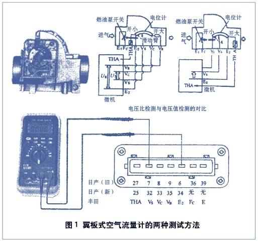
(1) Vane-type mass air flow sensors mainly have two types: One type outputs a signal voltage that increases with the increase in air flow; the other type outputs a signal voltage that decreases with the increase in air flow. Both types belong to analog voltage output. The vane-type mass air flow sensor is a three-wire sensor, where two wires are the positive and negative terminals of the reference voltage, and the other is the sliding contact arm of the potentiometer, which provides an output voltage signal proportional to the angle of the vane’s rotation to the computer. During rapid acceleration, the vane, under the dynamic pressure of the airflow, exceeds the normal swing angle, providing a control signal for enriching the mixture to the control computer. This is a very important sensor because the control computer uses this signal to calculate engine load, ignition timing, exhaust gas recirculation control, idle control, and other parameters. A faulty mass air flow sensor can cause engine stalling and poor idle, as well as performance and emission issues. Some models, such as Toyota’s vane-type mass air flow sensor, combine the fuel pump contact and intake temperature sensor, resulting in six output terminals, with its output voltage decreasing as the intake temperature increases.
Dynamic Testing Method for Vane-type Mass Air Flow Sensor: Turn off auxiliary electrical devices, start the engine, and let it idle until stable. Use the DC range of the automotive multimeter to measure the output terminal of the sliding contact arm and the negative terminal of the signal voltage. The output voltage at idle should be around 2V. Perform acceleration and deceleration tests. Increase the engine speed from idle to full throttle, maintaining full throttle for 2 seconds without exceeding the engine’s maximum speed. During acceleration, observe whether the voltage on the digital meter gradually jumps from 1V to about 4V; then reduce the engine speed to idle and hold for 2 seconds, the voltage reading during deceleration should drop to around 2V. At this point, press the (MAX/MIN dynamic record key) on the digital meter; the maximum voltage should be about 4V, and the minimum about 1V, indicating that the sensor is normal. If the maximum value is equal to or greater than 4.5±0.3V, it indicates that the flow meter signal error is too large; if the minimum value is 0, it indicates that there is an open circuit in the flow meter resistance. During full deceleration (rapid throttle release), the output voltage does not return very quickly from full acceleration voltage to idle voltage; generally (except for Toyota vehicles), the output voltage of the vane-type mass air flow sensor increases with the increase in intake volume.
Static Testing Method for Vane-type Mass Air Flow Sensor: For Toyota vehicles, turn on the ignition switch without starting the engine, and measure the output signal voltage VS using the DC voltage range. With the vane closed, the output voltage should be around 4V. Slowly push the vane with your hand; the output signal voltage VS should gradually decrease, and when the vane is fully open, the voltage should drop to around 0.5V. At this point, you can activate the maximum/minimum (MAX/MIN) function; if the maximum value reaches 5V or the minimum value is 0, it indicates a possible short circuit or open circuit in the sliding potentiometer. You can also disconnect the plug and measure the change in resistance of the sliding potentiometer to find the wear point.
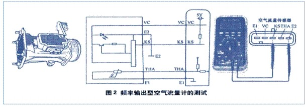
(2) Testing of Frequency Output Mass Air Flow Sensor: Locate the frequency signal output wire of the flow meter, set the automotive multimeter to the DC range, and use the function selection key (SELECT) to switch to the “DC+Hz” range. Start the engine and gradually accelerate while observing whether the main display shows DC voltage and the secondary display shows frequency changes with the speed. Generally, frequency-type mass air flow sensors change frequency with the increase in intake volume. There are exceptions, such as Mitsubishi vehicles, where the sensor is installed in the air filter, and both frequency and pulse width change with the intake volume. In this case, use the frequency “Hz” and duty cycle “DUTY” range adjustment function selection key (SELECT) to switch to the frequency duty cycle range while measuring the frequency and duty cycle of the mass air flow sensor.
2. Testing of Throttle Position Sensor
The throttle position sensor has two types: linear and switch type. The linear throttle position sensor (TPS) is a variable resistor that sends the throttle position signal to the engine ECU. The throttle switch signal consists of idle contact (IDL) and power contact (PSW). Most modern vehicles’ throttle position sensors are a combination of these two types, i.e., one idle contact and one variable resistor linear throttle position sensor combined. This is a very important sensor because the engine ECU uses its signal to calculate engine load, ignition timing, exhaust gas recirculation, and idle control. A faulty throttle position sensor can cause acceleration lag and unstable idle. Typically, the throttle position sensor generates a voltage signal of less than 1V when the throttle is closed and about 5V when fully open.

The testing of the throttle position sensor: Generally, at idle, the signal voltage is less than 1V, and at full throttle, it is less than 5V. Turn on the ignition switch without starting the engine, slowly move the throttle from closed to open several times, and check whether the voltage values are within the required range. You can also activate the maximum/minimum (MAX/MIN) function of the automotive multimeter to check if the minimum value is 0 and the maximum value is 5V.
3. Testing of Hall Sensor
The Hall sensor is an active sensor, and its output is essentially a switch signal output. It is not limited by speed; the output signal amplitude at low speed is the same as at high speed, making it widely used in crankshaft position, camshaft position, and other sensors. It consists of a nearly completely enclosed permanent magnet and magnetic circuit, with a magnetic blade rotor passing through the air gap between the magnetic poles, with notches distributed on the blade rotor. At the notches, the magnetic field acts on the Hall element, producing a signal output; when the blade rotor is not at the notch position, there is no magnetic field acting on the Hall element, resulting in no signal voltage output.
Testing of Hall Sensor: Both Hall and photoelectric sensors belong to frequency output type sensors and can measure the sensor frequency and duty cycle using the automotive multimeter’s “DUTY” and “Hz” ranges. The pulse amplitude of this sensor remains constant, while the frequency changes with speed. Turn on the ignition switch and test the three terminals of the Hall sensor; there should be 5V or 12V voltage between one terminal and another; after confirming, connect the red probe to the other terminal, set the automotive multimeter to the DC voltage range, and use the function conversion key to select “DC” and “Hz” to measure simultaneously while rotating the Hall sensor’s blade rotor. The frequency and voltage on the multimeter will be the output signal parameters of the Hall sensor, with the frequency increasing with the increase in speed.
4. Testing of Magnetic Electric Speed Sensor
The magnetic electric speed sensor is an analog AC signal generator that produces an AC signal. It generally consists of a coil and a magnet; when the iron ring gear rotates past the sensor, the coil generates an alternating voltage. The ABS wheel speed sensor is also magnetic electric, and its output signal amplitude and frequency increase with speed.
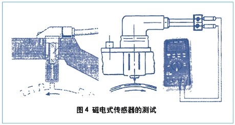
Testing of Magnetic Electric Speed Sensor: The main component of the magnetic electric sensor is the coil, so the first step is to test the resistance and continuity of the coil, which should be within the specified range. Test its signal output by setting the automotive multimeter to the AC range, and using the function conversion key to select “AC” and “Hz” to measure simultaneously. Allow the iron ring gear to rotate, and observe that the signal amplitude and frequency increase with speed; a small amplitude may be due to excessive sensor gap.
5. Testing of Oxygen Sensor
The oxygen sensor is an important feedback sensor in the electronic fuel injection system, detecting the concentration of oxygen in the exhaust gas and monitoring whether the engine burns according to the theoretical air-fuel ratio, feeding back to the engine ECU. It consists of a zirconia electrolyte that generates electromotive force and important electrodes. When the mixture is rich, there is less oxygen in the exhaust gas, and the difference in oxygen ions through the zirconia is large, generating a higher voltage; when the mixture is lean, there is more oxygen in the exhaust gas, and the difference in oxygen ions through the zirconia is small, generating a lower voltage.
 Oxygen Sensor Testing: Start the engine and let it run at 2500r/min for 90 seconds to preheat the oxygen sensor. Set the automotive multimeter to the DC mV range and measure the output voltage of the oxygen sensor; within 10 seconds, the sensor voltage should fluctuate more than 8 times between 100-900mV; otherwise, it indicates that the oxygen sensor is slow to respond.
6. Testing of Temperature Sensor
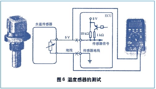
Temperature sensors are generally composed of negative temperature coefficient thermistors, providing a 5V power signal voltage to the engine ECU, returning a voltage signal inversely proportional to temperature.
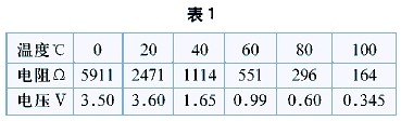
Testing of Temperature Sensor: The resistance values of various engines at different water temperatures should meet the specifications in Table 1 (different models may vary slightly, but the error is not significant). If they do not meet the specifications, it may cause difficulties in cold starts or hot starts, and issues with mixture richness or lean conditions.
The structure type, working principle, and detection methods of the intake temperature sensor are basically the same as those of the engine temperature sensor.
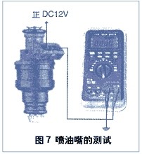
7. Testing of Fuel Injector
The fuel injector, as the main executing component of the injection system, directly affects the engine’s performance. When testing the fuel injector, set the automotive multimeter to the frequency (Hz) range, and use the secondary display key to select the positive and negative pulse trigger (ms) to test the pulse width of the fuel injector.
8. Testing of Fuel Pump Current
In actual maintenance, testing the working current of the fuel pump can help diagnose some intermittent faults. When testing, use the automotive multimeter’s current range (A), set the function key (SELECT) to the DC range, and connect it in series with the fuel pump circuit. While the fuel pump is working, press the dynamic record key (MAX/MIN). When abnormal fuel supply is detected while driving, observe the automatically recorded maximum and minimum current values to compare with normal values and identify the cause of the fault.

9. Testing of Idle Air Control Valve
The idle air control valve is generally controlled by the engine ECU, which adjusts its duty cycle to control its opening. During testing, select the frequency (DUTY—Hz) range, and use the 2nd VIEW (secondary display key) to adjust the positive and negative pulse duty cycle, checking whether the data meets the standards.

10. Simulation of Sensors and Driving of Actuators
The automotive multimeter has adjustable frequency and duty cycle square wave output functions, and external conversion modules can drive fuel injectors, ignition coils, ignition modules, engine tachometers, electronic odometers, and other actuators, as well as simulate tests for digital signals and voltage and resistance signals.
(1) Simulation of Mass Air Flow Sensor:
For digital mass air flow sensors: Identify the signal wire of the mass air flow sensor and determine whether it is a high-frequency or low-frequency type. If it is low-frequency, set the multimeter to the 50Hz range; if it is high-frequency, set it to the 2500Hz range. Switch the conversion module to the right positive pulse range, insert the red probe into the signal wire pulled from the sensor, and the black probe into the ground terminal pulled from the sensor, and observe the engine’s working state.
For voltage-type mass air flow sensors: Set the multimeter to the “V” range, switch the conversion module to the “VΩ” range, turn the knob counterclockwise to the low position, insert the red probe into the signal wire pulled from the sensor, and the black probe into the ground terminal pulled from the sensor. Turn the knob clockwise to adjust to the desired voltage value, and observe the engine’s working state.
(2) Simulation of Throttle Position Sensor:
The simulation of the throttle position sensor is the same as that of the voltage-type mass air flow sensor.
(3) Simulation of Water Temperature Sensor:
The water temperature sensor is a thermistor, and a variable resistor is used to simulate various water temperature signals sent to the computer. First, set the multimeter to the “Ω” range, connect the conversion module without connecting the power line; adjust the knob to display the required resistance value; then disconnect the module from the meter and use the red and black probes to supply the water temperature sensor for simulation.
It can also adjust the voltage for simulation, the method is: set the module to the “VΩ” range, and the multimeter to the “V” range; disconnect the water temperature sensor plug, and connect the red and black probes from the module to the 5V and ground lines on the plug; adjust the voltage knob. The lower the voltage, the higher the water temperature; the higher the voltage, the lower the water temperature, and observe the engine’s working state.
(4) Driving of Ignition Module:
For simulating ignition signals, set the multimeter to the 10Hz range, adjust the duty cycle to the range of 5%-10%, switch the conversion module to the right positive pulse range, and use the red and black probes to contact the ignition signal wire, observing the performance of the ignition module.
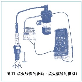
(5) Driving of Ignition Coil:
For simulating the ignition module: set the multimeter to the 10Hz—100Hz range, adjust the duty cycle to the range of 5%-10%; switch the conversion module to the left negative pulse range, and use the red probe to contact the negative terminal of the ignition coil, observing the performance of the ignition coil.
(6) Driving of Engine Tachometer and Electronic Odometer:
For simulating the tachometer and electronic odometer sensors: Most engine tachometers take their signal from the negative terminal of the ignition coil. Set the multimeter to the 10Hz range, switch the conversion module to the right positive pulse range; connect the red probe to the signal wire, adjust the multimeter’s frequency, and observe the performance of the tachometer. The electronic odometer and tachometer are the same.

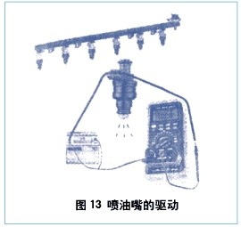
(7) Driving of Fuel Injector:
When driving the fuel injector, it can be driven individually or connected in parallel using custom wiring. However, when driving low-resistance (3-5Ω) fuel injectors or multiple injectors in parallel, the duty cycle must be set to the range of 5%-10%, and the specific method is the same as driving the ignition coil.
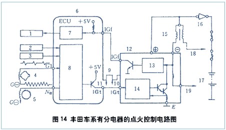
(8) Testing of Electronic Ignition System with Distributor:
Using the circuit diagram of the electronic ignition system with a distributor from Japanese Toyota vehicles as an example, we introduce the method of checking this system with an automotive multimeter: The principle of this circuit is that the engine ECU determines the ignition timing based on the crankshaft angle and other sensors. The engine ECU sends the ignition signal IGT to the ignition control unit. When the IGT signal becomes low, the primary current of the ignition coil is cut off, inducing high voltage in the secondary, which is then sent to each cylinder for ignition. This circuit also has functions for controlling ignition timing and ignition energy. When the primary current of the ignition coil is cut off, the primary coil generates a self-induction electromotive force triggering signal, and the ignition control unit outputs an ignition confirmation signal IGF to the engine ECU, which can monitor whether the ignition control circuit is functioning normally.
When this system fails, the simplest and most accessible areas should be checked first. Use the automotive multimeter to simulate the function to drive the ignition coil for inspection, then simulate driving the ignition control unit, applying the output signal to IGT, and observing the ignition coil’s firing condition. If the firing is normal, it indicates that the engine ECU did not send the ignition control unit the ignition signal IGT; if the firing is abnormal, check the ignition control unit’s ignition confirmation signal IGF. If there is no IGF signal, it is possible that the ignition control unit is damaged and cannot send the ignition confirmation signal to the engine control module, and without receiving the ignition confirmation signal, it cannot issue the fuel injection pulse.
The reference position signal G and speed signal Ne of the sensors inside the distributor should be checked: Since both of these sensors are magnetic electric, first measure the coil resistance. If both are normal, use the automotive multimeter’s signal simulation function to simulate the G and Ne signals separately to see if there is a high-voltage spark, thus determining the condition of these two sensors.
(9) Testing of Distributor-less Ignition (DLI) System:
Using the circuit diagram of the distributor-less DLI ignition system from Toyota vehicles as an example, we introduce the method of checking this system with an automotive multimeter: The system consists of a camshaft position sensor that detects the crankshaft angle, the control computer (ECU), and the ignition component. Based on the signal from the camshaft position sensor, it selects which cylinder should be ignited and sends the ignition signal to the ignition component, with the ignition coil directly supplying high voltage to the spark plug. The main feature of this system is that one ignition coil ignites two cylinders simultaneously, with one cylinder in exhaust, and that spark is a waste spark.
When this system fails, first determine whether the performance of these ignition coils is normal and whether the high-voltage line resistance is too high or damaged. Use the multimeter to drive the ignition coil to confirm its normal operation, then start the engine and check whether one ignition coil has no high voltage or if all have no high voltage. If it is a specific ignition coil, the fault may be in the ignition component; if all ignition coils have no high voltage, simulate the IGT ignition signal. If the ignition coil has high voltage and the IGF confirmation signal is normal, then simulate the camshaft position sensor and speed sensor. If there is still no high voltage, the fault may lie in the ECU.
1. Main Types of Automotive Electronic Signals
The electrical signals from the sensors and actuators of electronically controlled vehicles can be seen as the language of communication within the control system. The main types of automotive electronic signals include DC voltage signals, AC voltage signals, frequency modulation signals, pulse width modulation signals, and serial data signals. It is these electronic signals, utilizing their different characteristics, that achieve various communication purposes between sensors and the ECU, between the ECU and actuators, and between ECUs.
1. DC Voltage Signal (DC)
The sources of DC voltage signals in vehicles include batteries (12V) and reference voltages (5V) output by the ECU to sensors. Sensors that simulate DC voltage signals include: engine temperature sensor (ECT), fuel level sensor, intake temperature sensor (IAT), throttle position sensor (TPS), throttle switch, exhaust gas recirculation and position sensors, vane-type or hot wire mass air flow sensors (MAF), and intake pressure sensors (MAP), etc.
2. AC Voltage Signal (AC)
The sensors that generate AC voltage signals in vehicles mainly include: vehicle speed sensor (VSS), anti-lock brake wheel speed sensor, magnetic electric crankshaft position sensor (CKP), magnetic electric camshaft position sensor (CMP), and knock sensor (KS), etc.
3. Frequency Modulation Signal
The sensors that generate variable frequency signals in vehicles mainly include: digital mass air flow sensors, digital intake pressure sensors, photoelectric vehicle speed sensors (VSS), photoelectric crankshaft position sensors (CKP), photoelectric camshaft position sensors (CMP), Hall effect vehicle speed sensors (VSS), Hall effect crankshaft position sensors (CKP), and Hall effect camshaft position sensors (CMP), etc.
4. Pulse Width Modulation Signal
The circuits that generate pulse width modulation signals in vehicles mainly include: primary ignition coils, electronic ignition timing circuits, exhaust gas recirculation control valves (EGR), fuel injectors, idle control motors, evaporative canister solenoids (EVAP), turbochargers, and other solenoids.
5. Serial Data Signal
The serial data signals generated in automotive circuits by the engine control computer (PCM), body control computer (BCM), anti-lock brake system (ABS), or other computers have mutual transmission capabilities. It is the most complex among automotive electrical signals.
Click to read👉 A factory of 20 people generates 1 billion in annual output, with no worries about orders!
Automotive Parts Insider: qipeineican
Automotive Parts Insider popularizes various components of automobiles, explains automotive parts management, and the ways to profit from automotive parts! Join us in the automotive repair circle and automotive technology community!