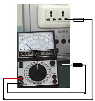
A multimeter is a magnetic-electric instrument equipped with a rectifier that can measure various electrical parameters such as AC and DC current, voltage, and resistance. Some models can also measure key parameters of transistors and capacitance. Mastering the use of a multimeter is one of the basic skills for electricians.
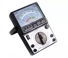
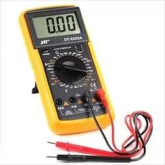
Let’s briefly introduce the basic functions using a digital multimeter as an example.
Measuring Voltage
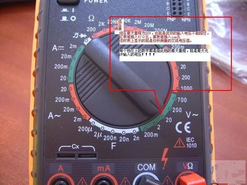
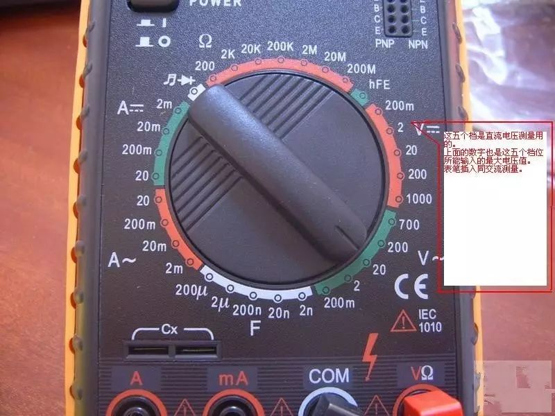
1. Insert the black probe into the COM port and the red probe into the VΩ port.
2. Turn the function rotary switch to V~ (AC), V- (DC), and select the appropriate range.
3. Touch the red probe to the positive terminal of the circuit being tested, and the black probe to the ground or negative terminal, effectively connecting in parallel with the tested circuit.
4. Read the digital display.
Measuring Resistance
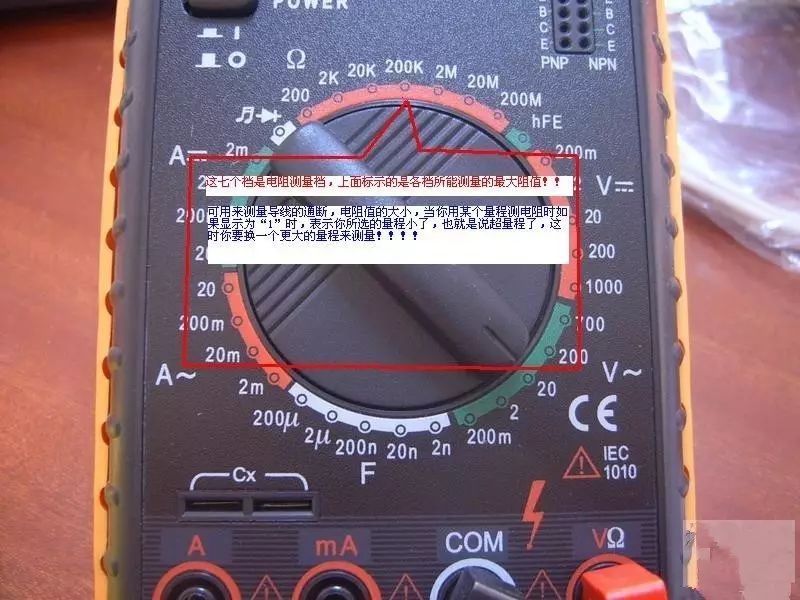
1. Turn off the power to the circuit.
2. Set the multimeter to the resistance range (Ω).
3. Insert the black test probe into the COM input socket and the red test probe into the Ω input socket.
4. Place the probe tips across the component or the section of the circuit you wish to measure.
5. Check the reading, confirming the measurement units – ohms (Ω), kilohms (kΩ), or megohms (MΩ).
Measuring Current
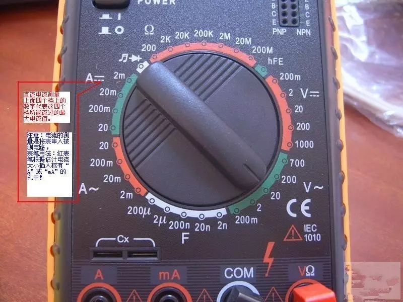
1. Disconnect the circuit;
2. Insert the black probe into the COM port and the red probe into the mA or 20A port;
3. Turn the function rotary switch to A~ (AC), A- (DC), and select the appropriate range;
4. Disconnect the tested circuit and connect the digital multimeter in series with the circuit, allowing current to flow from one end into the red probe and out of the black probe back into the circuit;
5. Reconnect the circuit;
6. Read the digital display.
Measuring Capacitance
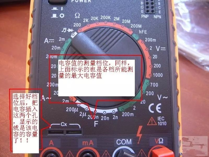
1. Short the terminals of the capacitor to discharge it, ensuring the safety of the digital multimeter.
2. Set the function rotary switch to the capacitance (C) measurement range and select the appropriate range.
3. Insert the capacitor into the C-X socket of the multimeter.
4. Read the number displayed on the LCD screen.
Small Knowledge: Units of capacitance:
1F = 1000mF = 1000uF = 1000nF = 1000pF
Function of the Diode Buzzer Mode
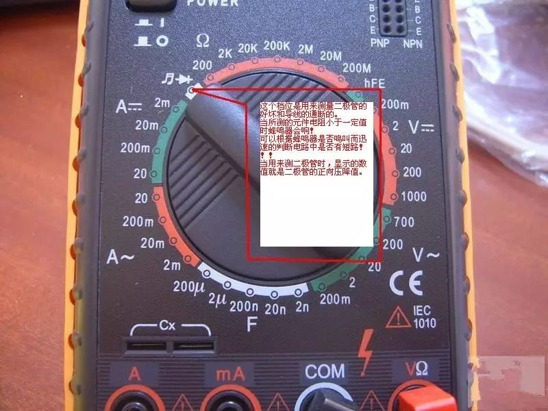
Judging the Condition of a Diode: Set the dial to the diode test ( ) position, insert the red probe into the rightmost socket and the black probe into the second socket from the right, then connect the tips of the probes to the two terminals of the diode and measure again by reversing the probes.
If the results of the two measurements are: one shows “1” and the other shows a number around zero, then this diode is a normal diode. If both measurements show the same result, then the diode is damaged, and the number displayed on the screen is the forward voltage drop of the diode: silicon materials around 0.6V; germanium materials around 0.2V. Based on the characteristics of the diode, it can be determined that the red probe is connected to the positive terminal of the diode, while the black probe is connected to the negative terminal.
Short Circuit Check (Judging Circuit Continuity): Set the dial to the short circuit ( ) position, with the same probe positions as above. Use the tips of the probes to touch the two points being tested. If these two points are indeed shorted, the buzzer in the multimeter will sound.
Precautions
1. If you cannot estimate the size of the voltage or current being measured beforehand, you should first set it to the highest range and measure once, then gradually reduce the range to an appropriate position based on the situation. After measurement, set the range switch to the highest voltage setting and turn off the power.
2. At full scale, the instrument will only display the number “1” at the highest position, with other positions disappearing. In this case, a higher range should be selected.
3. When measuring voltage, the digital multimeter should be connected in parallel with the circuit being tested. When measuring current, it should be connected in series with the circuit being tested, and when measuring DC, polarity does not need to be considered.
4. When mistakenly using the AC voltage range to measure DC voltage or vice versa, the display will show “000”, or the numbers at the lower position will fluctuate.
5. It is prohibited to change the range when measuring high voltage (above 220V) or large current (above 0.5A) to prevent arcing and burning the switch contacts.
After briefly introducing the basic usage of the multimeter, let’s introduce some application examples of the multimeter.
Using a Multimeter to Identify the Ends of Motor Windings
When the six output terminals of a three-phase asynchronous motor are lost or unclear in labeling, or after rewinding the windings, it is necessary to find out which two output terminals belong to the same phase, which is the start of the coil, and which is the end of the coil. Below are several operational methods to determine the start and end of the motor windings using a pointer multimeter.
Method 1
Use the multimeter in resistance mode to distinguish the two leads of each phase of the three-phase winding and assign hypothetical labels.
Observe the direction of the pointer movement on the multimeter (microamp range) when the switch is pressed. If the pointer swings to a value greater than 0, then the lead connected to the positive terminal of the battery and the lead connected to the negative terminal of the multimeter are either both the start or both the end. If the pointer swings in the opposite direction, then the lead connected to the positive terminal of the battery and the lead connected to the positive terminal of the multimeter are either both the start or both the end.
Then connect the battery and switch to the other two leads of the phase for testing, and you can correctly determine the start and end of each phase.
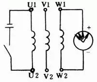
Method 2
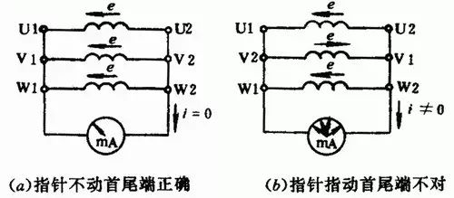
First, use the multimeter in resistance mode to distinguish the two leads of each phase of the three-phase winding. Assign hypothetical labels to each phase winding as U1, U2, V1, V2, and W1, W2. Connect according to the diagram below and judge the start and end. Rotate the motor rotor by hand; if the pointer on the multimeter (microamp range) does not move, it indicates that the hypothetical labeling is correct. If the pointer deflects, it indicates that one of the phase’s start and end labeling is incorrect, and you should swap and retest until correct.
Method 3
First, use the multimeter in resistance mode to distinguish the two leads of each phase of the three-phase winding and assign hypothetical labels, and connect according to the diagram below. Connect any two phase windings in series and then connect to the AC voltage range of the multimeter. Connect the third phase winding to a 36V low-voltage AC power supply.
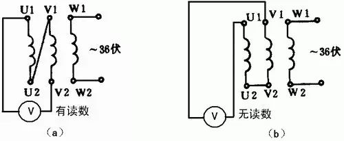
After powering on, if the voltmeter shows no reading, it indicates that the two leads connected together are both the start or both the end. If the voltmeter shows a reading, one of the two leads connected together is the start, and the other is the end. Designate one end as the known start, and the same method can be used to determine the start and end of the third phase.
Using a Multimeter to Determine Motor Speed and Poles
If the motor does not have a nameplate and there is no tachometer, the motor speed can be determined using a multimeter without disassembling the motor.
Using the minimum milliamp range of the multimeter, connect it to the previously determined start and end of a certain winding, and rotate the rotor slowly and uniformly. Observe how many times the multimeter pointer swings; if it swings once, it indicates that the current changes from positive to negative in one cycle, indicating it is a 2-pole motor. Similarly, if it swings twice, it indicates it is a 4-pole motor; if it swings three times, it indicates it is a 6-pole motor, and so on.
Once the number of poles of the motor is determined, the approximate speed can be known (slightly lower than the synchronous speed). The synchronous speed of the motor is related to the number of poles, and can be roughly calculated as follows for a power frequency of 50Hz: 2 poles = 3000r/min, 4 poles = 1500r/min, 6 poles = 1000r/min.
During operation, ensure good contact between the multimeter probes and terminals. Otherwise, the pointer may fluctuate during the rotation of the rotor, making it impossible to determine the result.
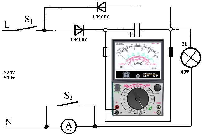
Using the DC Current Range to Measure AC Current
Many multimeters now have the function of measuring AC current, but many pointer-type multimeters only have DC current measurement capability. To meet measurement needs, by adding rectification and filtering circuits, the DC current range of the multimeter can be modified for AC current measurement within a certain range. The improved additional circuit is as follows:
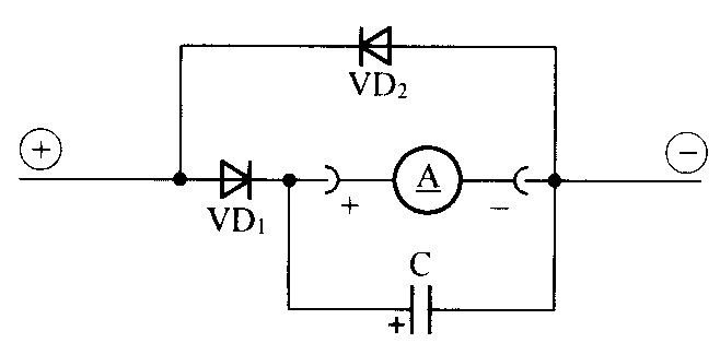
The circuit in the figure adds three components. Among them, VD1 is the rectifier diode, VD2 is the AC bypass diode, and C is the filter capacitor. The current passing through the DC ammeter is half-wave rectified current. If the negative half-wave bypass diode VD2 is not added, the test result will be slightly higher. Of course, if the test data does not require high accuracy, VD2 can be omitted. This simplifies the circuit. If the filter capacitor is not added, the pointer of the multimeter will oscillate.
The capacitance of capacitor C can be calculated and must reach an appropriate value to eliminate pointer jitter during measurement.
For ease of operation, we will use the following experimental circuit as an example to introduce the basic principles of using the multimeter’s DC current range to test AC current.
(1) Calculate the load working current. Based on the load power shown in the diagram, calculate the effective value of the AC current passing through the load as shown below:
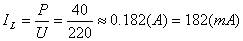
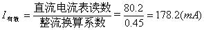
(2) Calculate the multimeter’s DC current range. Based on the relationship between the average value of half-wave rectification and the effective value (Iaverage=Ieffective×0.44), calculate the average current through the load HL as:
Iaverage=182mA×0.45=82mA
According to the principle that the range current value should be greater than the measured value, the multimeter’s DC current range can be set to the 100mA range.
(3) Turn on the power switch S1, the load is energized, the bulb EL lights up, and the multimeter indicates 80.2mA, while the AC ammeter A reads approximately 181mA.
(4) Close switch S2, the AC ammeter exits the test circuit, and check that the reading on the multimeter’s DC current range remains unchanged. The experiment ends successfully.
(5) Data processing. Divide the reading obtained from the fourth test by the half-wave rectification conversion coefficient to obtain the effective value of the AC current through the load.
If you frequently use the multimeter’s DC current range to test AC current, you can calculate the instrument constant based on the range of the multimeter’s DC current, which makes it very convenient to use.
|
DC Current Range |
Converted AC Current Range |
AC Range Instrument Constant |
|
50μA |
110μA |
2.2μA/scale |
|
0.5mA |
1.1mA |
22μA/scale |
|
5mA |
11mA |
220μA/scale |
|
50mA |
110mA |
2.2mA/scale |
|
500mA |
1100mA |
22mA/scale |
Experiments have proven that using the multimeter’s DC current range to test AC current is feasible, and the data is reliable. However, the reading from the multimeter’s DC current range is not the effective value of the AC current, but the average value of the AC current. The reading from the multimeter’s DC current range must be calculated to obtain the effective value of the AC current in the circuit.
Using a Multimeter to Locate Cable Breakpoints
When there is a broken line fault in a cable or its internal components, it is difficult to determine the exact location of the break due to the outer insulation cover. A digital multimeter can easily solve this problem.
The specific method is: connect one end of the wire (cable) with a breakpoint to the live wire of 220V AC power, leaving the other end suspended. Set the digital multimeter to the AC 2V range. Starting from the live wire connection point of the wire (cable), hold the black probe tip with one hand, while slowly moving the red probe along the wire’s insulation. The voltage displayed on the screen will be approximately 0.445V. When the red probe reaches a certain point, the displayed voltage will suddenly drop to about 0.0 volts (about one-tenth of the original voltage), indicating that the breakpoint of the wire (cable) is about 15cm forward (toward the live wire connection point).
When checking shielded wires with this method, if only the core wire is broken but the shielding layer is intact, this method will be ineffective.
This method can also be used to find the open circuit points of electric blankets and other resistive wires.
Using a Multimeter to Check for Moisture in Cables
During circuit maintenance, if the amplifier input level is lower than the specified loss value for the cable length, a pointer multimeter can be used in resistance mode to measure the resistance of the cable (R×1 or R×100 range). If the pointer rises slowly like a capacitor charging, this indicates that the cable is severely damp or has a significant amount of water inside.
Generally, a good cable should have an infinite resistance value. If the cable is severely damp and has a lot of water, its resistance value will be around hundreds of ohms; if the cable is filled with water, its resistance value will be nearly zero, equivalent to a short circuit, and the pointer will also rise slowly as if charging a capacitor. This indicates that the fault is due to moisture accumulation in the cable; at this point, the TV receiver will receive very poor signals, or even be unable to watch.
Disconnect the faulty cable at both ends, separating the inner and outer conductors. If there is a short circuit fault in the cable, the pointer will definitely point to zero; when the cable is open circuit, the other end of the cable should be shorted, and then measured with the multimeter. If the pointer still does not move, it proves that there is a break in that cable.
Damage to the outer plastic layer of coaxial cables due to construction or poor production quality can cause the plastic outer layer to crack and allow water ingress, leading to corrosion of the outer metal layer (or metal mesh). When checked with the multimeter’s resistance range, if the measured circuit resistance value is significantly higher than the original cable circuit value, it indicates serious corrosion of the outer conductor. If the measured circuit value is infinite, it indicates that the outer conductor has corroded and broken. In summary, there are many methods to test coaxial cables; as long as we analyze and judge carefully and master accurate testing methods, any fault can be detected.
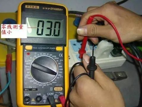
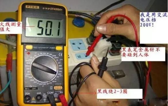
Using a Multimeter to Distinguish Between Phase and Neutral Wires
1. Using a Pointer Multimeter to Distinguish Phase and Neutral Wires
(1) Contact Measurement Method
Set the multimeter to the AC 250V or 500V range. Connect one probe to one end of the power supply and the other probe to the ground (such as a water pipe, radiator, or damp ground). If the grounding is good, when the multimeter reading is around 220V, the first probe is connected to the phase wire of the power supply, as shown in the figure below. If the pointer does not move, it indicates that the first probe is connected to the neutral wire. Even if the second probe has a high ground resistance, the pointer will show significant deflection when the first probe is connected to the phase wire.
Red probe connected to ground
(2) Non-contact Measurement Method
Set the multimeter to the AC 250V or 500V range. Connect one probe to either end of the power supply, and place the other probe on a table, holding the insulated handle part of the second probe (be careful not to touch the conductive part). If the first probe is connected to the phase wire, the pointer on the meter head can generally deflect by 2 to 10 scales, as shown in the figure below. The higher the sensitivity of the multimeter, the more pronounced the deflection. If the first probe is connected to the neutral wire, the pointer will not deflect.
The black probe should be placed on the table.
This method is applicable to any type of multimeter. This method poses no danger to the human body. This is because the internal resistance of the pointer multimeter is 20KΩ/V; if measuring a 220V voltage, the internal resistance of the pointer meter is 20KΩ × 220V = 4400Ω, which is relatively safe.
2. Using a Digital Multimeter to Distinguish Between Phase and Neutral Wires
The sensitivity of the AC voltage range of a digital multimeter is very high, and it can display even weak voltage signals on the LCD screen. Using the ACV range of the digital multimeter to find the phase wire of the AC power supply is intuitive, quick, accurate, and safe.
(1) Contact Measurement Method
Set the digital multimeter to the AC 20V range (or AC 2V range). Remove the black probe and insert it into the V/Ω socket. Hold the insulated handle of the red probe with one hand and touch the two sockets with the probe tip in turn. The one with the larger display value is the phase wire.
(2) Non-contact Measurement Method
Sometimes, it is necessary to find the phase wire from outdoor lighting lines; at this point, it is not necessary to strip the insulation of the wires. Use the red probe to touch the insulated outer skin of the two wires in turn; the one with the larger reading is the phase wire. Since it is an induced voltage, it is best to select the AC 2V range.
It is best to use a voltage tester (test pencil) to distinguish between phase and neutral wires!
Using a Multimeter to Detect Short Circuit Faults in Lighting Circuits
When there is a short circuit in the lighting circuit, the circuit current is very large, and the fuse quickly melts, cutting off the circuit. If the fuse is too thick, it can burn the wires and even cause a fire.
Possible causes of short circuits in lighting circuits include incorrect wiring, contact between phase and neutral wires; damage to the wire insulation, causing contact or grounding at the damaged point; internal damage to electrical appliances; loose metal contacts in lamp holders causing short circuits; water entering the lamp holder, etc.
We can use the resistance method to check where the fault is.
The resistance method involves using the multimeter’s resistance range to measure the resistance value between wires or electrical appliances to identify the short circuit location. After a short circuit occurs, the knife switch (or circuit breaker) on the distribution board should be turned off, and all electrical appliance plugs should be unplugged to completely cut off the power. Use the multimeter set to R×100 range to measure the resistance value between the phase and neutral wires. If the pointer approaches zero (or deflects), it indicates a short circuit (or leakage) in the circuit. Check the main line and each branch circuit section by section, and if necessary, disconnect a certain line and measure the resistance between the two wires to determine the fault location.
During repairs, first identify the short circuit point; use the multimeter’s resistance range to perform circuit segmentation and area checks in a powered-off state. Start testing from the load end towards the front end step by step to determine whether the problem is caused by the line or the components, so that it can be identified. After eliminating the short circuit fault point, reconnect qualified fuses and restore power.
Using a Multimeter to Detect Open Circuit Faults in Lighting Circuits
When there is an open circuit in the lighting circuit, there is no voltage in the circuit, the lighting does not illuminate, and electrical appliances cannot work. Causes include blown fuses, broken wires, loose connections, or damaged switches.
When using a multimeter to detect open circuit faults in lighting circuits, you can use the multimeter’s resistance range to measure the continuity of the circuit when the power is off; or you can measure the voltage of the circuit using the multimeter’s AC voltage range to determine the fault point while the power is on.
Open circuit faults in lighting circuits can be divided into complete open circuits, partial open circuits, and individual open circuits.
(1) Complete Open Circuit
This type of fault mainly occurs in the main line, within the range of distribution and metering devices, as well as the incoming device. Usually, the first step is to check each connection point in the aforementioned parts (including fuse connection terminals), where disconnection at the connection point is the most common fault; secondly, check the operation of the moving and static contacts of each circuit switch.
(2) Partial Open Circuit
This type of fault mainly occurs within the range of branch circuits. Generally, check each connection point first, and then check the branch switch. If the cross-section of the branch wire is small, consider that the core wire may be broken within the insulation layer, causing a partial open circuit.
(3) Individual Open Circuit
This type of fault is generally limited to the range of junction boxes, lamp holders, lamp switches, and the connecting wires between them. Usually, check each connection point separately, as well as the contact conditions of components such as lamp holders, lamp switches, and sockets (for fluorescent lamps, check the connections of each component).
Using a Multimeter to Detect Leakage Faults in Lighting Circuits
Once leakage occurs in the lighting circuit, it not only wastes electricity but may also lead to electric shock accidents. Leakage and short circuit are essentially the same, but the severity of the accidents differs. Severe leakage may cause a short circuit. Therefore, one should not take leakage in lighting circuits lightly; regular checks on the insulation condition of the circuit are necessary, especially when leakage is detected, the cause should be identified, the fault point found, and eliminated promptly.
The main causes of leakage in lighting circuits are: firstly, external damage to the insulation of wires or electrical equipment; secondly, aging and deterioration of insulation due to long-term operation; thirdly, moisture invasion or contamination of the circuit, leading to poor insulation.
First, determine whether there is indeed leakage. You can use a pointer multimeter in the R×10k range to measure the insulation resistance of the circuit, or set the digital multimeter to the AC current range (acting as a current meter), connecting it in series with the main switch, turning on all switches, and removing all loads (including bulbs). If there is current, it indicates leakage. After confirming the leakage in the circuit, continue the inspection using the following steps.
(1) Determine whether the leakage is between phase and neutral wires, or between phase and ground, or both. The method is to cut off the neutral wire; if the current meter reading remains unchanged, it indicates leakage between phase and ground; if the current meter reading is zero, it indicates leakage between phase and neutral; if the current meter reading decreases but is not zero, it indicates leakage between phase and neutral, and leakage between phase and ground.
(2) Determine the leakage range. Remove the branch fuse or open the circuit breaker; if the current meter reading remains unchanged, it indicates leakage in the main line; if the current meter reading is zero, it indicates leakage in the branch line; if the current meter reading decreases but is not zero, it indicates leakage in both the main and branch lines.
(3) Find the leakage point. After the above checks, sequentially turn off the switches of the lighting fixtures in that circuit. When a certain switch is turned off and the current meter reading returns to zero, it indicates that the branch line has leakage; if it decreases, it indicates that this branch line has leakage as well as leakage elsewhere; if all lighting fixture switches are turned off and the current meter reading remains unchanged, it indicates that the main line has leakage. Gradually narrow down the scope of the accident to further check the joints of that section of the circuit and the points where the wires pass through walls for leakage. Once the leakage point is found, promptly eliminate the leakage fault.
Lighting circuit short circuits, open circuits, and leakage are the most common faults. Only through specific measurements and analysis can we accurately find the fault point, determine the nature of the fault, and take effective measures to eliminate the fault as quickly as possible.
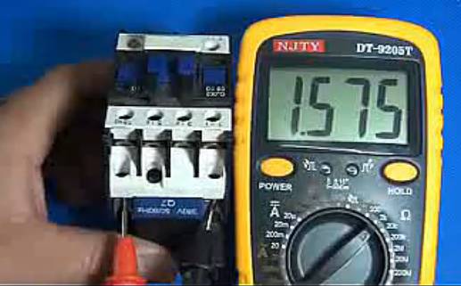
Using a Multimeter to Troubleshoot Power Drive Control Circuit Faults
1. Troubleshooting Power Drive Control Circuit Faults Using Resistance Measurement Method
(1) Measure the DC resistance value of components
In power drive control circuits, commonly used components include AC contactors, various relays, fuses, circuit breakers, control buttons, etc. We need to measure and record the DC resistance of the coils of AC contactors and various relays in the circuit (specific values vary significantly for different models of contactors; for example, the DC resistance of commonly used AC contactor coils is about 2000Ω, while newer models may only have a resistance of a few hundred ohms) for reference during repairs.
(2) Measure the continuity of the circuit
Before using the resistance method to find faults, first disconnect the control circuit from the control power supply, then set the multimeter to the R´10 or R´100 range to measure. Generally, use a segmented measurement method to check whether the circuit has faults.
The long segment method is used to measure the continuity of a certain branch; the short segment method is used to measure the continuity of one or several components in the branch. For example, press the button SB21 and measure the resistance between points 2 and 3 in the circuit; under normal conditions, the resistance should be 0Ω. If the measured resistance value is infinite, it indicates that SB1 has a break fault.
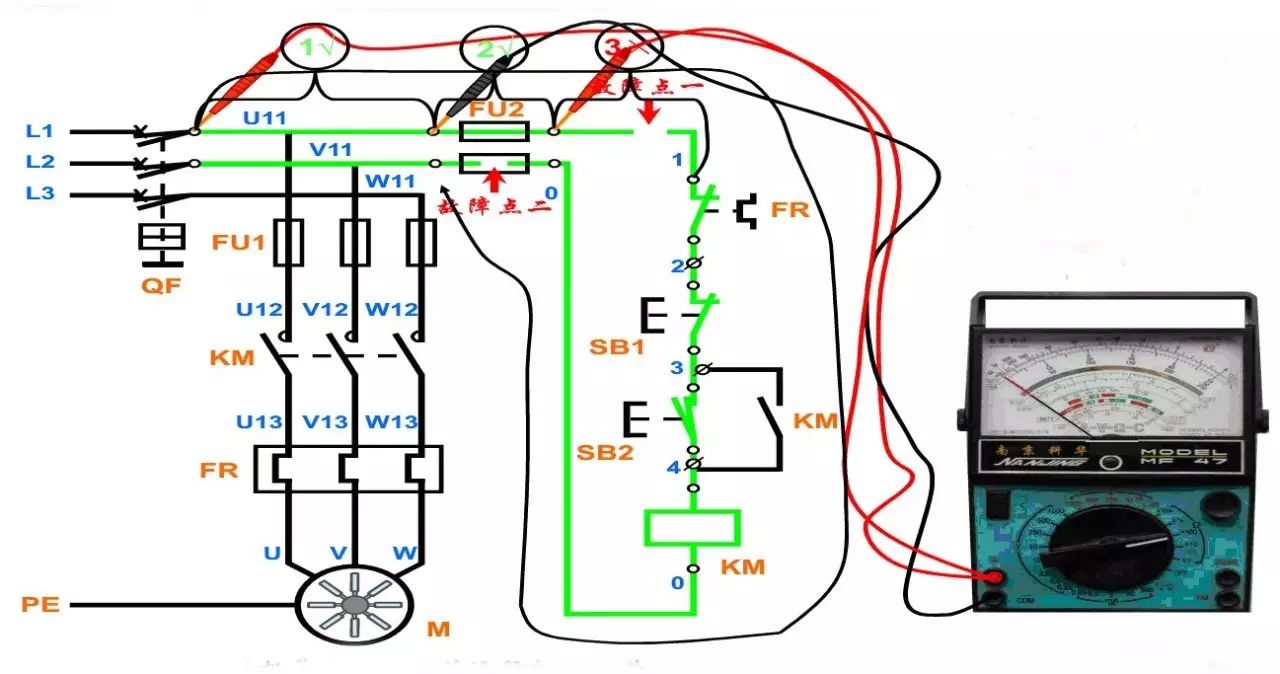
Application of Segmented Measurement Method
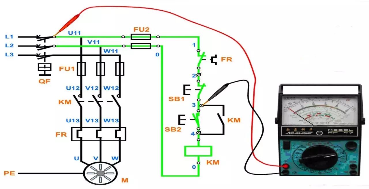
Checking the Control Circuit
Generally, the multimeter’s two probes are connected to the starting points of the control circuit, namely U11 and V11 of FU2 (or the output points 0 and 1 of FU2), press buttons and contactor position switches to simulate the operation of control elements. Based on the continuity of each branch, the controlled contactor coils and relay coils are connected in parallel or disconnected, and the changes in the resistance values indicated by the multimeter can be used to determine whether the circuit is normal.
Buttons, contactor self-locking functions, contactor interlocking functions, and the main circuit can be measured separately to check if the connections are correct. Connect the two probes of the multimeter to the starting points of the control circuit, namely U11 and V11 of FU2. If the reading on the multimeter indicates ∞ (if the resistance is 0Ω, it indicates a short circuit in the circuit; if the resistance is 2000Ω or 1000Ω, it indicates that the self-locking contacts or start button are incorrectly connected).
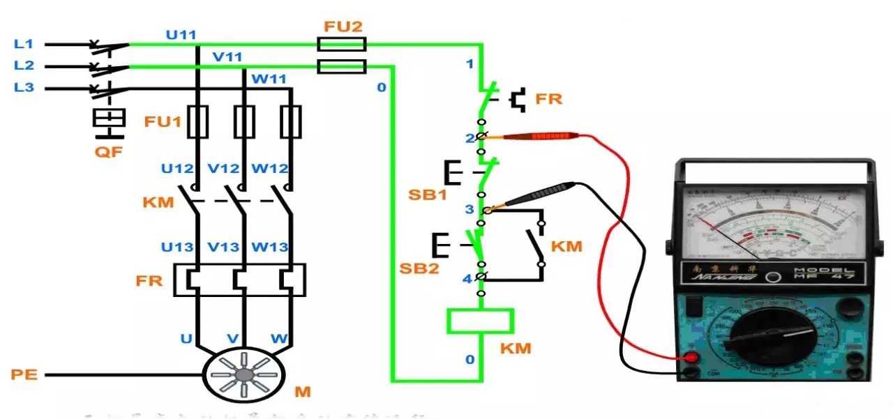
Checking the Main Circuit
Generally, the main circuit is checked after the control circuit has been checked, with the main goal of checking for short circuits in the main circuit. When checking the main circuit, since the DC resistance of each phase winding of the motor is relatively small, usually below 10Ω, the resistance range should be set to ×1Ω. After connecting to the motor, press the contactor’s working sequence to simulate the contactor’s operation while measuring the resistance between the total switch output points U11, V11, and W11. The resistance values should be equal and correspond to the resistance between any two power supply leads of the motor. If the resistance is zero, it indicates a short circuit in the main circuit; if the resistance is large or infinite, it indicates poor contact or an open circuit in the main circuit.
After measuring, if the resistance values conform to the above rules, the circuit wiring is basically correct with no serious faults (short circuits), and the success rate of powering on is very high. Meanwhile, during the measurement process, the level of circuit analysis and judgment is also improved.
2. Troubleshooting Power Drive Control Circuit Faults Using Voltage Measurement Method
(1) Basic Principles
The voltage measurement method involves using a multimeter to detect the working voltage in the circuit and comparing the measurement results with the normal values to determine whether the circuit is functioning normally.
When the circuit is functioning normally, the working voltage at various points in the circuit has a relatively stable normal value or a dynamic range of variation. If there is a short circuit fault, open circuit fault, or a change in the performance parameters of components in the circuit, the working voltage in that circuit will also change accordingly. Thus, the voltage measurement method can detect whether the working voltage at certain key points in the circuit is present or absent, whether it is too high or too low, and whether the dynamic changes are normal. Based on different fault phenomena, combined with the working principles of the circuit, the cause of the fault can be analyzed and identified.
(2) Basic Methods
The power supply is a necessary condition for the normal operation of the circuit. Therefore, when a fault occurs in the circuit, the power supply section should be checked first. If the power supply voltage is abnormal, the power supply circuit and load circuit should be checked for open circuit or short circuit faults. Generally, if there is an open circuit fault in the power supply section, such as a blown fuse, the power supply will have no voltage output; if the load has a short circuit fault, the power supply voltage will decrease.
When checking the power drive control circuit, set the multimeter to the AC voltage range of 500V. The voltage measurement method can be divided into stage measurement method and segment measurement method.
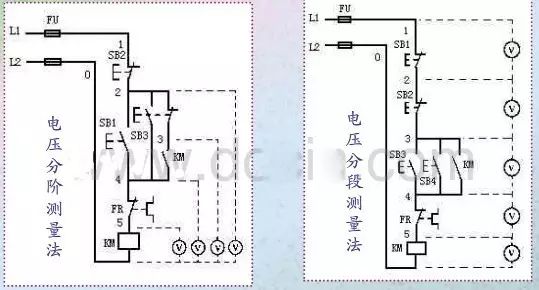
As shown in the left diagram above, when checking the voltage using the stage measurement method, first measure the voltage between points 1 and 0; if the voltage is normal, it should be 380V. Then, while holding the start button SB1, connect the black probe to point 0, and the red probe to points 2, 3, 4, and 5 in order, measuring the voltage between each stage. Under normal conditions, the voltage at each stage should be 380V.
As shown in the right diagram above, the voltage segment measurement method involves measuring the voltage between adjacent labeled points (for example, between 1 and 2, 2 and 3, 3 and 4, 4 and 5, and 5 and 0). If the circuit is normal, except for the voltage between points 5 and 6 being equal to 380V, the voltage between other adjacent points should be zero. If the contactor KM does not pull in when SB3 is pressed, it indicates a circuit open fault. At this point, the multimeter can be used to test the voltage between each adjacent pair of points. If a voltage of 380V is measured between any two adjacent points, it indicates that the contacts or connecting wires between those two points are poorly connected or open. For example, if the voltage between points 4 and 5 is 380V or a certain voltage value, it indicates that the contacts of the contactor KM are poorly connected or not conducting.
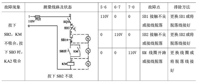
The application examples of the voltage measurement method are shown in the table below:
END
Due to space limitations, only a few points on the application of multimeters have been briefly mentioned. If you have more exciting content, feel free to share!
This article is excerpted from “Learning Multimeter Use Easily: Learning from Pictures”
Some images are sourced from the internet
If you like this article, please give a thumbs up for support
Mechanical Industry Press Electrical and Electronic Branch Official Operating Platform
Welcome to follow us

“Mechanical Industry Press E Vision” is committed to disseminating basic knowledge in the electrical field, hoping every follower can progress from beginner to expert!

“Science and Technology Eye” focuses on interpreting hot topics in the electrical industry and cutting-edge technology, helping you keep up with the times!
Click “Read the original text” to purchase related books