Siemens Comprehensive + TIA Portal + EPLAN Electrical Drawing Video Recordings for Sale at Low Prices!
Chuangkong Education Siemens Comprehensive Class Course Introduction
A multimeter, also known as a multi-tester, is a multifunctional and multi-range measuring instrument. Generally, a multimeter can measure DC current, DC voltage, AC voltage, resistance, and audio level, and some can also measure AC current, capacitance, inductance, and certain parameters of semiconductors (such as β).
AC voltage measurement: As shown in Figure 1, the maximum range is 20V, which means your input voltage cannot exceed this. The red probe is inserted into the v/Ω socket, and the black probe is inserted into the com socket. The value displayed on the meter is the AC voltage you are measuring.
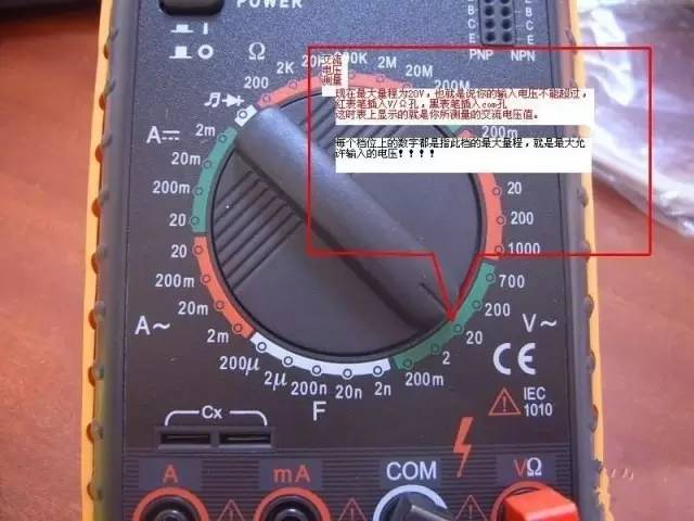
Figure 1
Figure 2 shows five ranges used for measuring DC voltage.
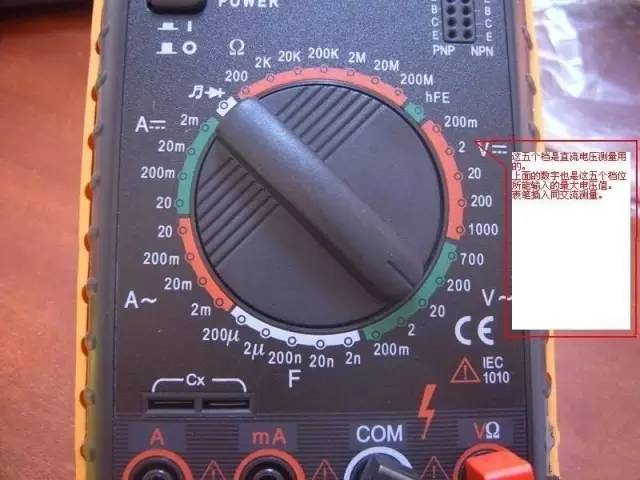
Figure 2
The numbers on the top four ranges for DC measurement represent the maximum current value that can flow through these ranges, as shown in Figure 3.
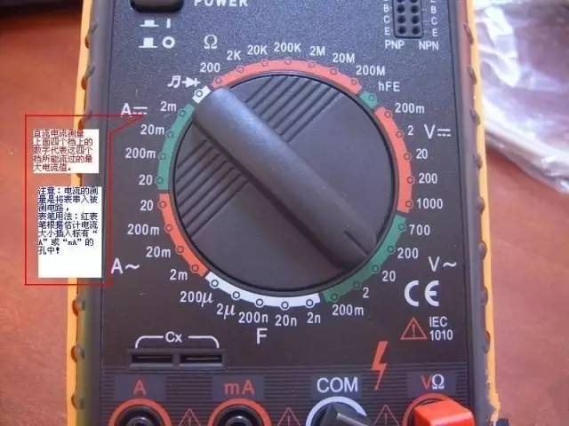
Figure 3
These seven ranges are for measuring resistance values, and the markings indicate the maximum resistance value that can be measured for each range, as shown in Figure 4.
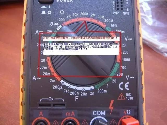
Figure 4
This range is used to test the good or bad condition of a diode and to check continuity, as shown in Figure 5.
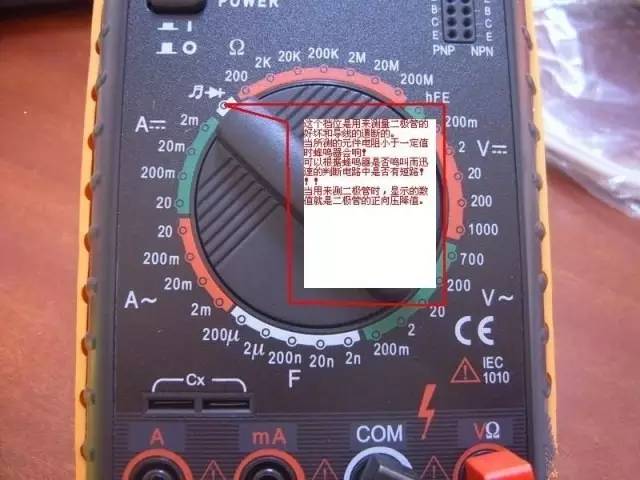
Figure 5
Figure 6 is the range for measuring capacitance, with the maximum capacitance value for each range indicated.
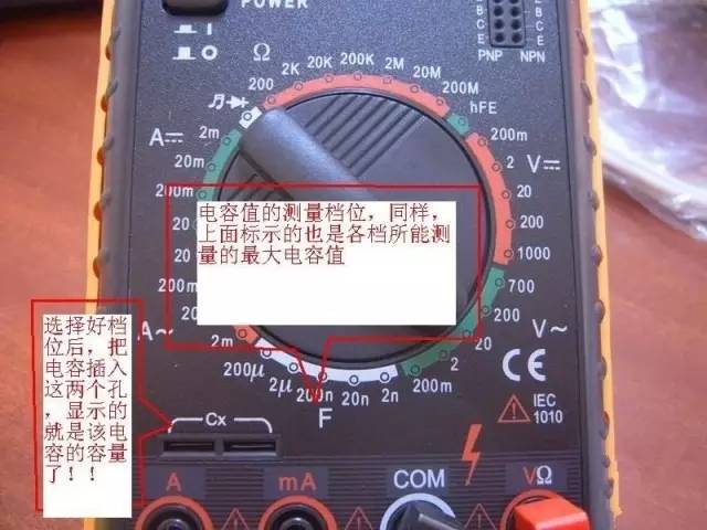
Figure 6
1. Structure of the Multimeter (Model 500)
A multimeter consists of three main parts: the meter head, measurement circuit, and selector switch.
(1) Meter Head
The meter head is a highly sensitive magnetic electric DC ammeter, and the main performance indicators of the multimeter are largely determined by the performance of the meter head. The sensitivity of the meter head refers to the value of the DC current that flows through the meter head when the pointer is fully deflected. The smaller this value, the higher the sensitivity of the meter head. The internal resistance when measuring voltage is higher, the better its performance. The meter head has four scale lines, which function as follows: The first line (from top to bottom) is marked R or Ω, indicating the resistance value when the selector switch is in the ohms position. The second line is marked ∽ and VA, indicating AC and DC voltage and DC current values when the selector switch is in the AC or DC voltage or DC current position, except for the AC 10V range. The third line is marked 10V, indicating the AC voltage value of 10V when the selector switch is in the AC voltage position at this range. The fourth line is marked dB, indicating audio level.
(2) Measurement Circuit
The measurement circuit is used to convert various measured values into suitable small DC currents for the meter head. It consists of resistors, semiconductor components, and batteries.
It can unify various different measurements (such as current, voltage, resistance, etc.) and different ranges into a certain limit of small DC current sent to the meter head for measurement after a series of processing (such as rectification, shunting, voltage division, etc.).
(3) Selector Switch
The function of the selector switch is to select various measurement circuits to meet different types and ranges of measurement requirements. Generally, there are two selector switches, each marked with different positions and ranges.
2. Symbol Meanings
(1) ∽ indicates AC and DC
(2) V-2.5KV 4000Ω/V indicates that for the AC voltage and 2.5KV DC voltage ranges, its sensitivity is 4000Ω/V
(3) A-V-Ω indicates that it can measure current, voltage, and resistance
(4) 45-65-1000Hz indicates the frequency range for use is below 1000 Hz, with a standard power frequency range of 45-65Hz
(5) 2000Ω/V DC indicates the sensitivity for the DC range is 2000Ω/V
The symbols on clamp meters and shaking meters are similar to the above symbols (other symbols cannot be fully written due to incorrect formatting).
3. Using the Multimeter
(1) Familiarize yourself with the meanings of each symbol on the dial and the main functions of each knob and selector switch.
(2) Perform mechanical zero adjustment.
(3) Depending on the type and size of the measurement, select the position and range of the selector switch and find the corresponding scale line.
(4) Choose the position of the test probes.
(5) Measuring Voltage: When measuring voltage (or current), ensure to select the appropriate range. If a small range is used to measure a large voltage, there is a risk of burning out the meter; if a large range is used to measure a small voltage, the pointer may deflect too little to read. The range selection should ideally make the pointer deflect to about 2/3 of full scale. If the size of the measured voltage is unknown beforehand, start with the highest range and gradually decrease to an appropriate range.
(a) Measuring AC Voltage: Set one selector switch to AC/DC voltage and the other to the appropriate AC voltage range, then connect the multimeter probes in parallel with the circuit or load being measured.
(b) Measuring DC Voltage: Set one selector switch to AC/DC voltage and the other to the appropriate DC voltage range, ensuring the “+” probe (red) is connected to the higher potential and the “-” probe (black) to the lower potential, allowing current to flow from the “+” probe to the “-” probe. If the probes are connected in reverse, the meter head pointer will deflect in the opposite direction, which may bend the pointer.
(6) Measuring Current: When measuring DC current, set one selector switch to the DC current position and the other to an appropriate range from 50μA to 500mA. The current range selection and reading method are the same as for voltage. Before measuring, the circuit must be interrupted, and the multimeter should be connected in series with the circuit being measured, allowing current to flow from the red probe to the black probe. If the multimeter is mistakenly connected in parallel with the load, due to the low internal resistance of the meter head, it may cause a short circuit and damage the instrument. The reading method is as follows:
Actual value = Indicated value × Range / Full scale deflection
(7) Measuring Resistance: When using a multimeter to measure resistance, follow these steps:
(a) Select the appropriate range. The ohms scale of the multimeter is not uniform, so the range selection should allow the pointer to stop in the less dense part of the scale, and the closer the pointer is to the middle of the scale, the more accurate the reading. Generally, the pointer should be positioned between 1/3 and 2/3 of the scale.
(b) Zero adjustment for ohms. Before measuring resistance, short-circuit the two probes and adjust the “ohms (electrical) zero adjustment knob” so that the pointer points exactly to the zero position just to the right of the ohms scale line. If the pointer cannot be adjusted to zero, it indicates insufficient battery voltage or a problem within the instrument. Moreover, each time the range is changed, the ohms zero adjustment should be performed again to ensure accurate measurement.
(c) Reading: The reading of the meter head multiplied by the range gives the resistance value measured.
(8) Precautions
(a) When measuring current or voltage, do not change the range while the circuit is live.
(b) When selecting a range, start with a larger range and then move to a smaller one, aiming to have the measured value close to the range.
(c) Do not measure resistance while the circuit is live. When measuring resistance, the multimeter is powered by its internal battery; measuring live would be equivalent to connecting an additional power source, which may damage the meter head.
(d) After use, ensure the selector switch is set to the maximum AC voltage position or the off position.
4. Digital Multimeter
Now, digital measuring instruments have become mainstream and are trending to replace analog instruments. Compared to analog instruments, digital instruments have higher sensitivity, accuracy, clear display, strong overload capacity, are portable, and are easier to use. Below, we briefly introduce the usage and precautions of the VC9802 digital multimeter as an example.
(1) Usage
a. Before use, carefully read the relevant user manual to familiarize yourself with the power switch, range switch, sockets, and the functions of special sockets.
b. Set the power switch to the ON position.
c. Measuring AC/DC voltage: Depending on your needs, set the range switch to the appropriate DCV (direct current) or ACV (alternating current) range, insert the red probe into the V/Ω socket and the black probe into the COM socket, then connect the probes in parallel with the circuit being measured; the reading will be displayed.
d. Measuring AC/DC current: Set the range switch to the appropriate DCA (direct current) or ACA (alternating current) range, insert the red probe into the mA socket (for <200mA) or 10A socket (for >200mA), insert the black probe into the COM socket, and connect the multimeter in series with the circuit being measured. When measuring direct current, the digital multimeter can automatically display polarity.
e. Measuring resistance: Set the range switch to the appropriate Ω range, insert the red probe into the V/Ω socket and the black probe into the COM socket. If the measured resistance exceeds the maximum value of the selected range, the multimeter will display “1”; at this point, a higher range should be selected. When measuring resistance, the red probe is positive, and the black probe is negative, which is the opposite of the analog multimeter. Therefore, when measuring polarized components such as transistors and electrolytic capacitors, it is essential to pay attention to the polarity of the probes.
(2) Precautions
a. If you cannot estimate the size of the voltage or current to be measured in advance, first set it to the highest range and measure once, then gradually reduce the range to an appropriate position based on the situation. After measuring, set the range switch to the highest voltage position and turn off the power.
b. At full range, the instrument will only display the digit “1” at the highest position, while other positions will disappear; at this point, a higher range should be selected.
c. When measuring voltage, the digital multimeter should be connected in parallel with the circuit being measured. When measuring current, it should be connected in series with the circuit being measured; when measuring direct current, polarity does not need to be considered.
d. If the AC voltage range is mistakenly used to measure DC voltage, or if the DC voltage range is mistakenly used to measure AC voltage, the display will show “000” or the digits at the lower position will fluctuate.
e. It is prohibited to change the range while measuring high voltage (above 220V) or large current (above 0.5A) to prevent arcing and damaging the switch contacts.
f. When the display shows “ ”, “BATT”, or “LOW BAT”, it indicates that the battery voltage is below the operating voltage.
5. Shake Meter
A shake meter, also known as a megohmmeter, is used to measure the insulation resistance and high resistance of the device being tested. It consists of a hand-cranked generator, a meter head, and three terminals (i.e., L: line terminal, E: grounding terminal, G: shielding terminal).
1) Selection Principles for Shake Meters
(1) Selection of rated voltage level. Generally, for equipment with a rated voltage below 500V, a shake meter rated at 500V or 1000V should be selected; for equipment with a rated voltage above 500V, a shake meter rated at 1000V to 2500V should be selected.
(2) Selection of resistance range. The scale line of the shake meter has two small black dots, and the area between the small dots is the accurate measurement area. Therefore, when selecting a meter, ensure that the insulation resistance value of the tested device falls within the accurate measurement area.
2) Using the Shake Meter
(1) Calibration. Before measurement, perform an open circuit and short circuit test on the shake meter to check if it is functioning correctly. Open the two connecting wires, turn the handle, and the pointer should point to “∞”; then short the two connecting wires, and the pointer should point to “0”. If it meets the above conditions, it is good; otherwise, it cannot be used.
(2) The device being measured must be disconnected from the circuit, and for large capacitor devices, it must be discharged.
(3) Select a shake meter that meets the voltage rating.
(4) When measuring insulation resistance, generally only the “L” and “E” terminals are used, but when measuring the insulation resistance of cables to ground or when the leakage current of the device being tested is significant, the “G” terminal should be used, connecting the “G” terminal to the shielding layer or casing. After connecting the circuit, turn the crank clockwise, starting slowly and then increasing speed. When the speed reaches about 120 revolutions per minute (for the ZC-25 model), maintain a constant speed, read the value after one minute, and read while cranking; do not stop to read.
(5) Discharge the line after reading. After reading, slowly crank while disconnecting the lines, then discharge the device being measured. The discharge method is to take the ground wire used during measurement off the shake meter and short it to the device being measured (not the shake meter discharging).
3) Precautions
(1) It is prohibited to measure insulation resistance during thunderstorms or near high-voltage equipment; measurements can only be made when the equipment is not energized and there is no induced voltage.
(2) During the shaking measurement process, no one should work on the device being tested.
(3) The shake meter wires should not be twisted together; they should be separated.
(4) Before the shake meter stops rotating or before the measured device is discharged, do not touch with your hands. When disconnecting the wires, do not touch the metallic parts of the leads.
(5) At the end of the measurement, large capacitor devices must be discharged.
(6) Regularly verify its accuracy.
6. Clamp Meter
A clamp meter is an instrument used to measure the current size of an electrical line that is running, allowing current measurement without interrupting the power supply.
1) Structure and Principle
A clamp meter essentially consists of a current transformer, a clamp-shaped wrench, and a rectifying magnetic electric system with feedback.
2) Usage
(1) Perform mechanical zero adjustment before measurement.
(2) Select the appropriate range, starting with a larger range and then moving to a smaller one or estimating based on the nameplate value.
(3) When measuring with the smallest range, if the reading is not significant, you can wrap the measured wire a few times; the number of turns should be based on the number of turns at the center of the clamp, so the reading = indicated value × range / full scale deflection × number of turns.
(4) During measurement, ensure the measured wire is centered in the clamp and that the clamp is closed tightly to reduce errors.
(5) After measuring, set the selector switch to the highest range position.
3) Precautions
(1) The voltage of the measured line must be lower than the rated voltage of the clamp meter.
(2) When measuring the current of high-voltage lines, wear insulated gloves, insulated shoes, and stand on an insulated mat.
(3) The clamp must be closed tightly; do not change the range while energized.
Sharing is the greatest encouragement! Thank you for your support!
(Content source: Internet, copyright belongs to the original author)
Disclaimer: If there are copyright issues, please contact for deletion!Neither individuals nor organizations bear related legal responsibilities.
Siemens Comprehensive + TIA Portal + EPLAN Electrical Drawing Video Recordings for Sale at Low Prices!
Chuangkong Education Siemens Comprehensive Class Course Introduction