A multimeter is a common electrical measuring instrument. In addition to its common uses, there are some lesser-known applications. Here is a complete summary of these uses:
The multimeter can be used to determine if a circuit or device is live. By selecting the appropriate measurement mode and contacting the circuit with the probes, voltage presence and magnitude can be detected, ensuring safe operation.
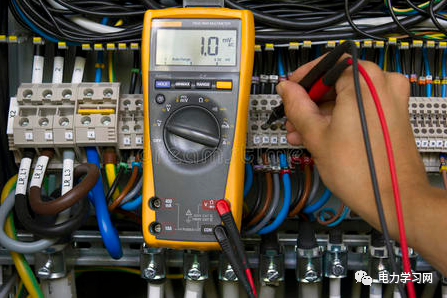
Usage:Select the voltage measurement mode, touch the probes to the two contact points or conductors to be tested, and read the voltage value displayed on the screen. If a voltage is displayed, it indicates that the circuit is live.
The multimeter can be used to distinguish between the live wire and neutral wire in an AC power source. This is crucial for proper wiring during the installation and maintenance of electrical equipment.
Usage:Select the voltage measurement mode, touch one probe to the wire to be tested, and the other probe to the ground wire or the grounding part of the device. If a voltage is displayed, it indicates that the wire being tested is the live wire.
The multimeter can be used to locate breakpoints or faults within cables. This is very useful for troubleshooting and repairing wires.
Usage:Select the resistance measurement mode, touch the probes of the multimeter to the two ends of the cable to be tested, and read the resistance value displayed on the screen. If the resistance is infinite (open circuit), it indicates a breakpoint exists.
The multimeter can be used to test the quality and stability of the power supply to assess its suitability.
Usage:Select the voltage measurement mode, touch one probe to the positive terminal of the power supply, and the other probe to the negative terminal, then read the voltage value displayed on the screen. Observe the stability and fluctuations of the voltage to evaluate the performance of the power supply.
The multimeter can be used to detect the intensity of electromagnetic radiation from nearby electronic devices, power lines, or wireless communication devices.
Usage:Select the appropriate electromagnetic radiation measurement mode and detector, place the detector of the multimeter in the area of interest, and read the electromagnetic radiation intensity value displayed on the screen.
The multimeter can be used to test the capacity of a battery to determine its remaining charge and performance.
Usage:Select the appropriate voltage measurement mode, touch the probes of the multimeter to the positive and negative terminals of the battery, and read the voltage value displayed on the screen. By comparing with the battery’s rated voltage, one can assess the battery’s capacity status.
The multimeter can be used to measure the temperature coefficient of resistance, which indicates how the resistance value changes with temperature.
Usage:Select the resistance measurement mode, touch the probes of the multimeter to the resistance element, measure its resistance value. Then heat or cool the element and measure the resistance value again. By comparing the resistance values at two temperatures, the temperature coefficient of resistance can be calculated.
The multimeter can be used to determine the polarity of a light-emitting diode (LED) to ensure proper connection.
Usage:Select the diode measurement mode, touch the probes of the multimeter to the two leads of the LED. If a forward voltage value appears on the display, it indicates that the probe is touching the positive lead; otherwise, it is the negative lead.
The multimeter can be used to test parameters like capacitance of capacitors or inductance of inductors.
Usage:Depending on the type of component being tested, select the appropriate measurement mode and range. Touch the probes of the multimeter to the leads of the component and read the values displayed on the screen to obtain the parameter values.
The multimeter can be used to detect fault voltage waveforms in a circuit to determine if there are any anomalies or distortions.
Usage:Select the appropriate voltage measurement mode and range, touch the probes of the multimeter to the voltage signal in the circuit to be tested. Observe the waveform displayed on the screen to detect distortion, noise, or other issues with the voltage waveform.
The multimeter can be used to test the input and output states of logic gates (such as AND, OR, NOT gates) to verify if the logic operations of the circuit are correct.
Usage:Select the appropriate voltage measurement mode and range, touch the probes of the multimeter to the input and output terminals of the logic gate. Based on the voltage values displayed on the screen, the input and output states of the logic gate can be determined.
The multimeter can be used to calibrate other instruments and equipment to ensure their accuracy and precision.
Usage:By comparing with a standard source with known accurate values, adjust the measurement range, zero point, and gain parameters of the instruments and equipment to ensure their output meets the expected accurate values.
Some multimeters have a light intensity testing function that can be used to measure the brightness or illuminance of light sources for lighting design and environmental light detection.
Usage:Select the appropriate light intensity testing mode and range, expose the light-sensitive element of the multimeter to the light source or lighting environment to be tested. Observe the light intensity values displayed on the screen to assess the brightness level or illuminance value of the light source.
The multimeter can be used to diagnose faults in sensors, such as temperature sensors, pressure sensors, humidity sensors, etc.
Usage:Depending on the type and specifications of the sensor, select the appropriate testing mode and range, connect the multimeter to the sensor. Observe the values or signal changes displayed on the screen to determine if the sensor is functioning properly.
Some multimeters have the function to test pulse width, which can be used to measure the duration of high or low levels of pulse signals.
Usage:Select the appropriate pulse width testing mode and range, touch the probes of the multimeter to the positive and negative terminals of the pulse signal. Observe the pulse width values displayed on the screen to evaluate the stability of the signal and the characteristics of the pulse width.
In some cases, the polarity of a capacitor may be damaged or unclear.
Usage:By touching the testing leads of the multimeter to the two leads of the capacitor, one can check the capacitor’s polarity. If the displayed voltage is positive, it indicates that the positive lead is connected to the red testing lead, and the negative lead is connected to the black testing lead; vice versa.
Usage:By touching the testing leads of the multimeter to the two leads of the LED, one can measure the brightness of the LED. The brightness of the LED is proportional to the current, so measuring the current can help assess the brightness level of the LED.
Usage:Using the capacitance measurement function of the multimeter, one can detect faulty or damaged capacitors. By measuring the capacitance value of the capacitor, one can determine if it is functioning normally or has failed.
Phase Sequence:Select the voltage testing function of the multimeter, connect the testing leads to the three phases of the three-phase power supply. By reading the voltage values displayed on the screen and observing their order, one can determine if the phase sequence of the three-phase power supply is correct.
Usage:Select the voltage testing function of the multimeter, connect the testing leads to the control terminals of the relay. By varying the control voltage, observe the relay’s pull-in and release conditions to determine its pull-in and release voltage range.
精彩阅读
电压kV为什么k要小写,原因你知道吗?

发一份德国的电气图纸,看一下与我国的区别在哪里

什么是三段式电流保护?

万用表使用口诀,绝对干货!

双电源供电与双回路供电的区别是什么?
电路老祖宗, 把它搞懂了,其他电路你也就懂了

500KW电机运转无力,查了三天的故障,被一个新电工搞定了!

10kV线路故障快速查找口诀,建议收藏!