New friends click on the blue text “Mechanical Industry Press E Vision” to follow
1. Identifying the Start and End of Motor Windings with a Multimeter
When the six output terminals of a three-phase asynchronous motor are lost or unclear, or when the windings are rewound, it is necessary to determine which two output terminals belong to the same phase, which is the start of the coil, and which is the end of the coil. Below are several operational methods.
Method 1: Resistance Measurement
Use the multimeter in resistance mode to distinguish the two wire ends of each phase of the three-phase winding and assign hypothetical numbers. Connect as shown in the figure below.
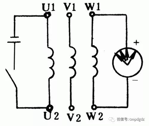
Observe the direction of the pointer swing on the multimeter in microamp mode. At the moment the switch is closed, if the pointer swings to the side greater than 0, then the wire connected to the positive terminal of the battery and the wire connected to the negative terminal of the multimeter are both either the start or end. If the pointer swings in the opposite direction, then the wire connected to the positive terminal of the battery and the wire connected to the positive terminal of the multimeter are both either the start or end.
Then connect the battery and switch to the other two wire ends of the same phase for testing, which will correctly identify the start and end of each phase.
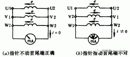
Method 2: Hypothetical Numbering
First, use the multimeter in resistance mode to distinguish the two wire ends of each phase of the three-phase winding. Assign hypothetical numbers to each phase winding as U1, U2, V1, V2, and W1, W2. Connect as shown in the figure below to determine the start and end. Rotate the motor rotor with your hand; if the pointer on the multimeter (in microamp mode) does not move, it proves that the hypothetical numbering is correct. If the pointer deflects, it indicates that one of the phase’s start and end hypothetical numbers is incorrect, and you should swap and retest until correct.
Method 3: Series Connection
First, use the multimeter in resistance mode to distinguish the two wire ends of each phase of the three-phase winding and assign hypothetical numbers, and connect as shown in the figure below. Connect any two phase windings in series and then connect to the AC voltage setting of the multimeter, while connecting the third phase winding to a 36V low-voltage AC power supply.
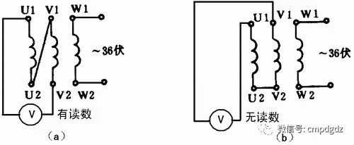
After powering on, if the voltage meter shows no reading, it indicates that the two connected wire ends are both the start or end. If the voltage meter shows a reading, then one of the two connected wire ends is the start and the other is the end. Designate one end as the known start, and the same method can be used to determine the start and end of the third phase.
2. Using a Multimeter to Determine Motor Speed and Pole Count
If the motor has no nameplate and no tachometer, the speed of the motor can be determined using a multimeter without disassembling the motor.
The method is: use the minimum milliamp setting on the multimeter to connect the previously identified start and end of a certain winding, and slowly rotate the rotor one full circle, observing how many times the pointer on the multimeter swings. If it swings once, it indicates a positive and negative current change over one cycle, which means it is a 2-pole motor. Similarly, if it swings twice, it indicates a 4-pole motor; if it swings three times, it indicates a 6-pole motor, and so on.
Once the number of poles of the motor is determined, the approximate speed can be calculated (slightly lower than the synchronous speed). The relationship between the synchronous speed of the motor and the number of poles can be calculated as follows: for a frequency of 50Hz, the synchronous speeds are 3000r/min for 2 poles, 1500r/min for 4 poles, and 1000r/min for 6 poles.
During operation, ensure good contact between the multimeter probes and terminals. Otherwise, the pointer will swing during the rotor’s rotation, making it impossible to determine the result.
3. Measuring AC Current Using the DC Current Setting
1. Multimeter Circuit Improvement
Many analog multimeters only have DC current testing capabilities and lack AC current testing functionality. To meet measurement needs, adding rectification and filtering circuits can convert the DC current setting of the multimeter to AC current measurement within a certain range. The improved additional circuit is shown in the figure below.
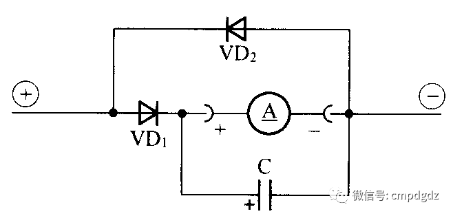
The circuit in the figure adds three components. VD1 is a rectifier diode, VD2 is an AC bypass diode, and C is a filter capacitor. The current through the DC ammeter is half-wave rectified. If the negative half-wave bypass diode VD2 is not added, the test results will be slightly higher. Of course, if the testing data does not require high accuracy, VD2 can be omitted, simplifying the circuit. If the filter capacitor is not added, the pointer of the multimeter will oscillate.
The capacity of capacitor C can be calculated and must reach an appropriate value to eliminate the pointer’s jitter during measurement.
2. Measuring AC Current with the Improved Multimeter
For ease of operation, we will use the experimental circuit shown in the figure below to introduce the basic principles of testing AC current using the DC current setting of the multimeter.
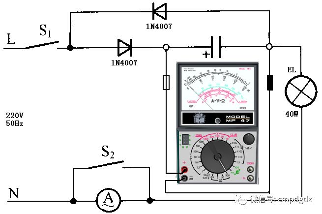
(1) Determine the load operating current. According to the load power shown in the figure, calculate the effective value of the AC current through the load to be 182mA.
(2) Determine the range of the multimeter’s DC current setting. Based on the relationship between the average value of half-wave rectification and the effective value, calculate the average current through the load EL to be 82mA.
According to the principle that the range current value must be greater than the measured value, the multimeter’s DC current range can be set to the 100mA setting.
(3) Close the power switch S1, the load is energized, the bulb EL lights up, and the multimeter indicates 80.2mA, while the AC ammeter A reads about 181mA.
(4) Close switch S2, disconnect the AC ammeter from the test circuit, and observe that the reading on the multimeter’s DC current setting remains unchanged. The test concludes successfully.
(5) Data processing. Divide the reading obtained from the DC ammeter in step four by the half-wave rectification conversion coefficient to obtain the effective value of the AC current through the load.
If the use of the multimeter’s DC current setting to test AC current is frequent, the constants for the instrument can be calculated based on the ranges of the multimeter’s DC current settings for convenience. Taking the MF30 type multimeter as an example, the half-wave rectification conversion coefficient is taken as 0.45, as shown in the table below.
|
DC Current Range |
Converted AC Current Range |
AC Range Instrument Constant |
|
50μA |
110μA |
2.2μA/Division |
|
0.5mA |
1.1mA |
22μA/Division |
|
5mA |
11mA |
220μA/Division |
|
50mA |
110mA |
2.2mA/Division |
|
500mA |
1100mA |
22mA/Division |
For example, if the MF30 type multimeter is set to the DC current 500mA range and operates in half-wave rectification mode, testing a certain AC load current, it is found that the pointer of the multimeter indicates 38 divisions, to calculate the effective value of the AC current.
From the table, the AC range instrument constant for the DC current 500mA range is 22mA/Division, so the effective value of the AC current through the load in the tested circuit is 836mA.
Tests have shown that using the multimeter’s DC current setting to measure AC current is feasible, and the data is reliable. However, the reading on the multimeter’s DC current setting is not the effective value of the AC current but rather the average value of the AC current, and the reading must be calculated to obtain the effective value of the AC current in the circuit.
4. Using a Multimeter to Locate Cable Breakpoints
When a cable or its internal wires experience a break fault, due to the external insulation, it can be difficult to determine the exact location of the break. The traditional method is to use the multimeter’s resistance mode to search for the cable break point segment by segment, which not only wastes time but can also significantly damage the cable’s insulation. A digital multimeter can easily solve this problem.
The specific method: connect one end of the faulty wire (cable) to the live wire of the 220V mains, leaving the other end open. Set the digital multimeter to AC 2V mode, starting from the live wire connection point, hold the black probe’s tip with one hand while moving the red probe along the wire’s insulation with the other hand. At this point, the voltage displayed on the screen is approximately 0.445V (as measured by the DT890D model). When the red probe moves to a certain point, the voltage displayed on the screen suddenly drops to about 0.0V (approximately one-tenth of the original voltage), and the breakpoint of the wire (cable) is about 15cm forward (toward the live wire connection point) from that position.
This method is ineffective when checking shielded wires if only the core wire is broken but the shielding layer remains intact.
This method can also be used to locate breakpoints in faulty electric heating blankets and other resistance wires.
5. Using a Multimeter to Check for Moisture in Cables
When repairing circuits, if the input level of the amplifier is lower than the specified loss value for the cable length, the resistance of the cable can be measured using the resistance mode of the analog multimeter (R×1 or R×100 range). If the pointer rises slowly like a capacitor charging, this phenomenon indicates that the cable is severely damp or has a lot of accumulated water inside.
Generally speaking, an intact cable should have an infinite resistance value. If the cable is severely damp with a lot of water, its resistance value is usually in the hundreds of ohms; if the cable is filled with water, its resistance value is basically zero, equivalent to a short circuit, and the pointer will also slowly rise like a capacitor charging. This can definitively determine that the fault is caused by moisture accumulation in the cable; at this time, the TV receiver will receive very poor TV signal quality, or even be unable to watch.
Remove the faulty cable with an open circuit or short circuit from both ends, separating the internal and external conductors. If the cable has a short circuit fault, the pointer will definitely point to zero; when the cable is open, the other end of the cable should be shorted, and then check with the multimeter. If the pointer still does not move, it proves that there is a break in that cable.
Due to construction damage to the plastic outer layer of coaxial cables or due to poor production quality, the thickness of the cable’s plastic outer layer varies. After exposure to sun and rain, the thinner areas of the outer layer crack and allow water to enter, causing corrosion of the outer metallic layer (or metallic mesh). When checking this fault with the multimeter in resistance mode, if the measured loop resistance is significantly higher than the original cable loop value, it proves that the outer conductor is severely corroded. If the measured loop value is infinite, it indicates that the outer conductor has broken after corrosion. In summary, there are many methods for testing coaxial cables; as long as we analyze and judge carefully, we can find any faults.
6. Distinguishing Live and Neutral Wires with a Multimeter
Using an Analog Multimeter to Distinguish Live and Neutral Wires
1. Contact Measurement Method
Set the multimeter switch to the AC 250V or 500V range. Connect the first probe to one end of the power supply, and the second probe to the ground (such as a water pipe, radiator, or damp ground). If the grounding is good, when the multimeter reading is around 220V, the first probe is connected to the live wire, as shown in the figure (a). If the pointer does not move, it indicates that the first probe is connected to the neutral wire. Even if the second probe has a large grounding resistance, the pointer will show a significant deflection when the first probe is connected to the live wire.
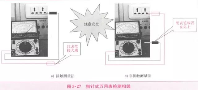
2. Non-contact Measurement Method
Set the multimeter switch to the AC 250V or 500V range. Connect the first probe to either end of the power supply, and place the second probe in the air on the table, holding the insulated part of the second probe with your hand (be careful not to touch the conductive part). If the first probe is connected to the live wire, the pointer on the meter will usually deflect 2 to 10 divisions, as shown in the figure (b). The higher the sensitivity of the multimeter, the more pronounced the deflection. If the first probe is connected to the neutral wire, the pointer will not deflect.
This method is applicable to any model of multimeter and poses no danger to the human body. This is because the internal resistance of the analog multimeter is 20K/V; if used to measure 220V, the internal resistance of the analog meter would be 20K×220V=4400, which is relatively safe.
3. Precautions
The best way to distinguish between live and neutral wires is to use a voltage tester, which is a quick and safe method.
When using an analog multimeter to distinguish between live and neutral wires, safety must be prioritized. Specifically, the insulation of the probe wires should be good, and the operator’s hands and any part of the body should not come into direct contact with the metallic parts of the probes to avoid electric shock risks.
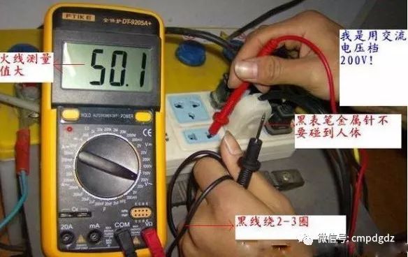
Using a Digital Multimeter to Distinguish Live and Neutral Wires
As we know, the sensitivity of the AC voltage range of a digital multimeter is very high, and even weak voltage signals can be displayed on the LCD screen. Using the ACV setting of a digital multimeter to find the live wire has the advantages of being intuitive, quick, accurate, and safe.
1. Contact Measurement Method
Set the digital multimeter to the AC 20V range (or AC 2V range), remove the black probe, and insert it into the V/Ω socket. Holding the insulated handle of the red probe with one hand, touch the tips of the probes to the two sockets sequentially; the one with the larger display value is the live wire, as shown in the figure below.
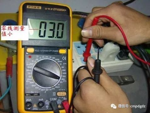
2. Non-contact Measurement Method
Sometimes, it is necessary to find the live wire from outdoor lighting wires; at this time, there is no need to strip off the insulation of the wire. Use the red probe to sequentially touch the insulated outer skin of the two wires; the one with the larger reading is the live wire. Since this is an induced voltage, it is best to select the AC 2V range.
7. Using a Multimeter to Detect Short Circuit Faults in Lighting Circuits
1. Fault Phenomena and Causes
When a short circuit occurs in the lighting circuit, the current in the circuit becomes very large, causing the fuse to blow quickly and the circuit to be cut off. If the fuse is too thick, it may burn the wires or even cause a fire.
Possible causes of short circuits in lighting circuits include: wiring errors, contact between live and neutral wires; damage to the insulation layer of wires, causing contact or grounding at the damaged point; internal damage to electrical appliances; loose metal pieces inside the lamp holder causing short circuits, water entering the lamp holder, etc.
2. Using a Multimeter to Locate Short Circuit Faults
The phenomena of short circuit faults in lighting circuits are quite obvious, but determining the location of the fault can be complex. We can use the resistance method to check for faults.
The resistance method involves using the resistance mode of the multimeter to measure the resistance values between wires or electrical appliances to determine the location of the short circuit. After a short circuit occurs, disconnect the knife switch (or circuit breaker) on the distribution board, and unplug all appliances to completely cut off the power. Set the multimeter to R×100 range and measure the resistance value between the live and neutral wires. If the pointer tends to zero (or deflects), it indicates that there is a short circuit (or leakage) in the circuit. Check the main line and each branch circuit section by section, and if necessary, disconnect a certain line and measure the resistance between the two wires to determine the location of the fault.
During repairs, first locate the short circuit point by using the resistance mode of the multimeter to conduct circuit segment and area checks while the power is off. Start from the load end and check step by step towards the front end to determine whether the issue is caused by the line or the components, which will help identify the fault. After eliminating the short circuit fault point, reconnect the qualified fuse and restore power.
8. Using a Multimeter to Detect Open Circuit Faults in Lighting Circuits
1. Fault Phenomena and Causes
When an open circuit occurs in the lighting circuit, there is no voltage in the circuit, the lights do not illuminate, and electrical appliances cannot operate. The causes include: blown fuses, broken wires, loose wire ends, damaged switches, etc.
2. Troubleshooting Open Circuit Faults
When using a multimeter to detect open circuit faults in lighting circuits, you can use the resistance mode to measure the continuity of the circuit while the power is off; or measure the voltage using the AC voltage setting while the power is on to determine the fault point.
Open circuit faults in lighting circuits can be classified into three categories: complete open circuit, partial open circuit, and individual open circuit.
(1) Complete Open Circuit.
This type of fault mainly occurs on the main line, within the distribution and metering devices, and within the scope of the incoming device. Generally, you should first check each connection point in the aforementioned parts (including the fuse connection points) in sequence, as the disconnection of wire ends is the most common fault; secondly, check the on-off conditions of the contact points of various line switches.
(2) Partial Open Circuit.
This type of fault mainly occurs within the branch circuit range. Generally, first check the connection points of each wire end, and then check the branch switch. If the cross-section of the branch wire is small, consider that the core wire may have broken within the insulation layer, causing a partial open circuit.
(3) Individual Open Circuit.
This type of fault is generally limited to the connection points of junction boxes, lamp holders, lamp switches, and the connecting wires between them. Typically, check each connection point and the contact conditions of components such as lamp holders, lamp switches, and sockets (for fluorescent lamps, check the connection of each component).
9. Using a Multimeter to Detect Leakage Faults in Lighting Circuits
1. Causes of Leakage in Lighting Circuits
Once leakage occurs in the lighting circuit, it not only wastes electricity but may also lead to electric shock accidents. Leakage is fundamentally the same as short circuit, just at different stages of the incident development; severe leakage may cause a short circuit. Therefore, leakage in lighting circuits should not be taken lightly, and the insulation condition of the circuit should be checked regularly. Especially when leakage is detected, the cause should be promptly identified, and the fault point should be eliminated.
The main causes of leakage in lighting circuits are: damage to the insulation of wires or electrical equipment due to external forces; aging and deterioration of insulation due to long-term operation; moisture intrusion or contamination of the circuit, resulting in poor insulation.
2. Troubleshooting Leakage Faults
First, determine whether leakage is indeed occurring. You can measure the insulation resistance of the circuit using the R×10k setting of an analog multimeter, or set a digital multimeter to the AC current setting (which acts as a current meter) and connect it in series with the main switch, turning on all switches and removing all loads (including bulbs). If there is current, it indicates that leakage is present. Once leakage in the circuit is confirmed, further checks can be conducted based on the following steps.
(1) Determine whether leakage is between the live and neutral wires, or between the live wire and ground, or both. The method is to cut off the neutral wire; if the current meter reading remains unchanged, it indicates leakage between the live wire and ground; if the current meter reading is zero, it indicates leakage between the live and neutral wires; if the current meter reading decreases but is not zero, it indicates leakage between the live wire and neutral, as well as between the live wire and ground.
(2) Determine the scope of leakage. Remove the branch fuse or trip the circuit breaker; if the current meter reading remains unchanged, it indicates leakage in the main line; if the current meter reading is zero, it indicates branch leakage; if the current meter reading decreases but is not zero, it indicates leakage in both the main and branch lines.
(3) Locate the leakage point. After the above checks, sequentially disconnect the switches of the circuit lights; when disconnecting a certain switch, if the current meter reading returns to zero, it indicates that the branch line is leaking; if it decreases, it indicates that this branch line is leaking and there is leakage elsewhere; if all lamp switches are turned off and the current meter reading remains unchanged, it indicates that the main line is leaking. Narrow down the accident scope step by step to check whether there are any leakage points at the joints of that segment of the line or where the wires pass through walls. Once the leakage point is identified, the fault should be eliminated promptly.
Short circuits, open circuits, and leakage in lighting circuits are the most common faults. Only through specific measurements and analysis can we accurately find the fault points, determine the nature of the faults, and take effective measures to eliminate the faults as quickly as possible.
10. Using a Multimeter to Repair Power Drive Control Circuit Faults
Using the Resistance Measurement Method to Repair Power Drive Control Circuit Faults
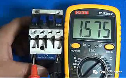
1. Measuring the DC Resistance Values of Components
In power drive control circuits, common components include AC contactors, various relays, fuses, circuit breakers, control buttons, etc. We must measure and record the DC resistance of the coils of AC contactors and various relays used in the circuit (the specific values vary significantly for different models of contactors; for example, the DC resistance of commonly used AC contactor coils is about 2000Ω, while the coils of newer models may only be a few hundred ohms), for reference during repairs, as shown in the figure below.
2. Measuring the Continuity of the Circuit
Before using the resistance method to locate fault points, first disconnect the control circuit from the control power supply, and then set the multimeter to R×10W or R×100W range to measure. Generally, a segmented measurement method is used to check whether the circuit has faults, as shown in the figure below.
(a) Segmented Measurement One
(b) Segmented Measurement Two
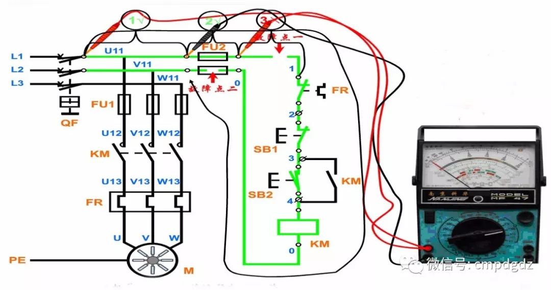
(c) Segmented Measurement Three
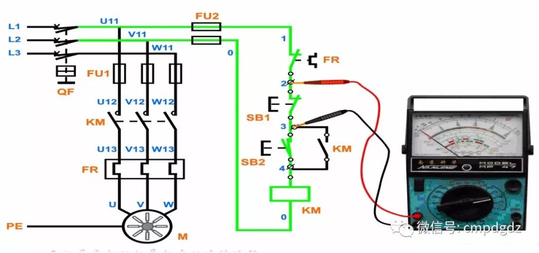
The long-segment method is used to measure the continuity of a certain branch; the short-segment method is used to measure the continuity of one or more components in the branch. For example, when pressing the button SB21, measure the resistance between points 2 and 3 in the circuit; under normal conditions, the resistance should be 0Ω. If the measured resistance value is infinite, it indicates that SB1 has an open circuit fault, as shown in figure b.
3. Checking the Control Circuit
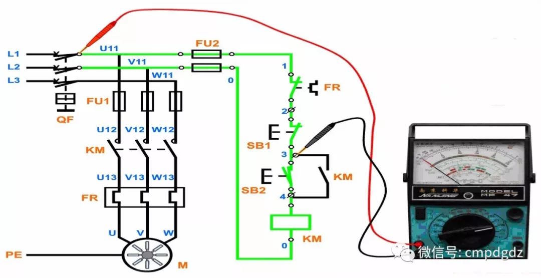
Generally, the multimeter’s two probes are connected to the starting points of the control circuit, namely points U11 and V11 of FU2 (or the output points 0 and 1 of FU2). By pressing the button and simulating the operation of the control elements, the controlled contactor coils and relay coils will form parallel or disconnected states based on the continuity of each branch, and the resistance values indicated by the multimeter can be used to determine whether the circuit is normal.
You can measure the functions of buttons, the self-locking function of contactors, the interlocking function of contactors, and the main circuit to conduct the checks. Connect the multimeter’s two probes to the starting points of the control circuit, namely points U11 and V11 of FU2. If the multimeter reading indicates ∞ (if the resistance is 0Ω, the circuit has a short circuit; if the resistance is 2000Ω or 1000Ω, it may indicate that the self-locking contact or the start button is incorrectly connected).
4. Checking the Main Circuit
Generally, this is done after checking the control circuit, mainly to check whether there is a short circuit in the main circuit. When checking the main circuit, since the DC resistance of each phase winding of the motor is relatively small, usually below 10Ω, the resistance mode should be set to ×1Ω range. After connecting to the motor, simulate the operation of the contactor by pressing the contactor’s contact point in the correct sequence, while measuring the resistance between the output points U11, V11, and W11 of the main switch. The resistance values should be equal and correspond to the resistance between any two power supply wires of the motor. If the resistance is zero, it indicates a short circuit in the main circuit; if a large resistance or ∞ is indicated, it indicates poor contact or an open circuit in the main circuit.
After measurement, if the resistance values conform to the above rules, the circuit wiring is basically correct, and there are no serious faults (short circuits), the success rate of powering on is very high. Additionally, during the measurement process, the level of circuit analysis and judgment is improved.
The multimeter should be set to an appropriate range; if the range is too large, the reading will be too small, leading to a misjudgment of a short circuit; if the range is too small, the reading will be very large, leading to a misjudgment of an open circuit, which can severely affect measurement accuracy. Generally, the ×10Ω or ×100Ω ranges should be selected.
Before powering on and testing, the voltage measurement method should be used to check whether the output voltage of each fuse is normal. If it is not normal, the cause should be identified. When the control circuit is functioning normally, it is essential to measure whether the voltage at the output terminals connected to the motor is normal to avoid phase loss when the motor is powered on.
Using the Voltage Measurement Method to Repair Power Drive Control Circuit Faults
1. Basic Principle of Voltage Measurement Method
The voltage measurement method involves using a multimeter to detect the working voltage in the circuit, comparing the measured results with normal values to determine whether the circuit is functioning correctly.
When the circuit is functioning normally, the working voltage at various points in the circuit has a relatively stable normal value or a dynamically varying range. If a short circuit fault, open circuit fault, or change in the performance parameters of components occurs in the circuit, the working voltage in that circuit will also change accordingly. Therefore, the voltage measurement method can detect whether certain key points in the circuit have voltage, whether the voltage is too high or too low, and whether the dynamic changes are normal. Based on different fault phenomena and the working principles of the circuit, analysis can be conducted to identify the cause of the fault.
2. Basic Methods of Voltage Measurement
The power supply is a necessary condition for the normal operation of the circuit. Therefore, when a fault occurs in the circuit, the power supply section should be checked first. If the power supply voltage is abnormal, it is essential to check whether there are open circuit or short circuit faults in the power supply circuit and the load circuit. Generally, if there is an open circuit fault in the power supply section, such as a blown fuse, the power supply will have no voltage output; if the load has a short circuit fault, the power supply voltage will decrease.
When checking power drive control circuits, set the multimeter to the AC voltage range of 500V. The voltage measurement method can be divided into stage measurement method and segment measurement method, as shown in the figure below.
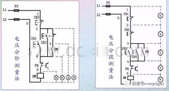
As shown in figure a, when using the voltage stage measurement method, first measure the voltage between points 1 and 0 with the multimeter. If the voltage is normal, it should be 380V. Then, while holding down the start button SB1, connect the black probe to point 0 and sequentially move the red probe to points 2, 3, 4, and 5, measuring the voltage between each stage. Under normal conditions, the voltage at each stage should be 380V.
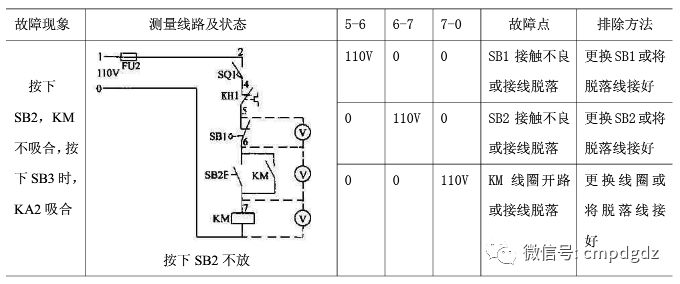
As shown in figure b, the voltage segment measurement method involves sequentially measuring the voltage between adjacent marked points (for example, 1 to 2, 2 to 3, 3 to 4, 4 to 5, and 5 to 0). If the circuit is normal, except for the voltage between points 5 and 6 being 380V, all other adjacent points should have a voltage of zero. If pressing the SB3 contactor KM does not engage, it indicates that there is an open circuit fault in the circuit. At this point, the multimeter should be used to test the voltage between each adjacent pair of points. If a voltage of 380V is measured between any two adjacent points, it indicates that the contact points and connecting wires between those two points have poor contact or are open. For example, if the voltage between points 4 and 5 is 380V or a certain voltage value, it indicates that the contact points of the contactor KM have poor contact or are not conducting.
The application examples of the voltage measurement method are shown in the table below.
(1) When using the voltage measurement method to detect the circuit, it is essential to understand the condition of the circuit being measured and the voltage range, and then reasonably select the range of the multimeter based on the actual situation to avoid damaging the multimeter.
(2) Before measuring, it is crucial to distinguish whether the measured voltage is AC or DC, ensuring that the red probe is connected to the higher potential test point and the black probe to the lower potential test point to prevent damage to the multimeter due to reverse bias.
(3) When using the voltage measurement method, precautions should be taken to prevent electric shock. During measurement, the human body should not touch the metallic parts of the probes. In practice, it is generally recommended to fix the black probe in place and use one hand to hold the red probe for measurement.
END
Everyone can supplement the article with explanations that are incorrect or lacking in the comments section, so that the next person who sees it can learn more. What you know is exactly what everyone needs…
If you encounter problems while studying or working, you can join our WeChat group for discussion, exploration, and learning together! The group has exceeded 100 people, and you cannot join independently; please contact the editor to add you to the group.

Click “Read the Original” to purchase books related to multimeters