
Click the blue text
Follow us
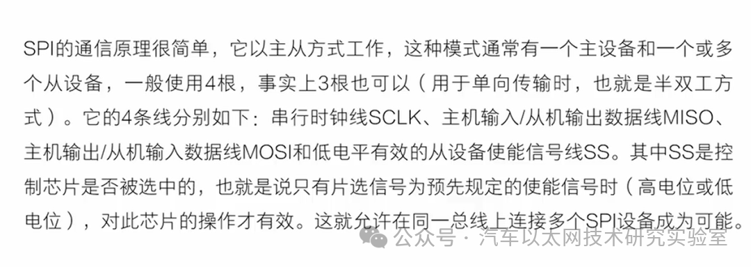
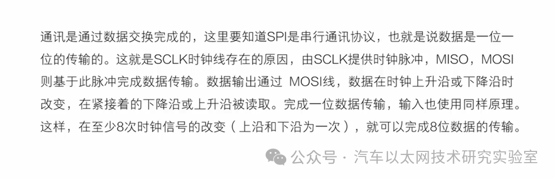
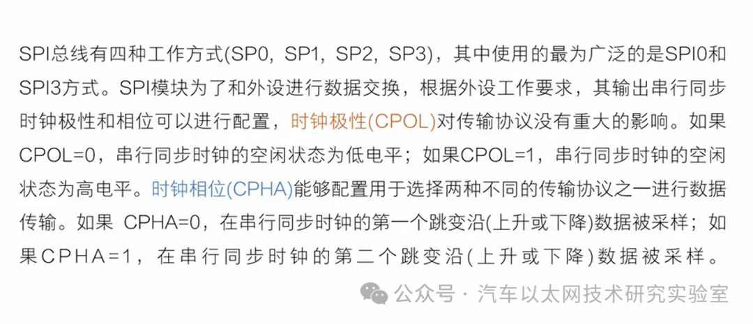
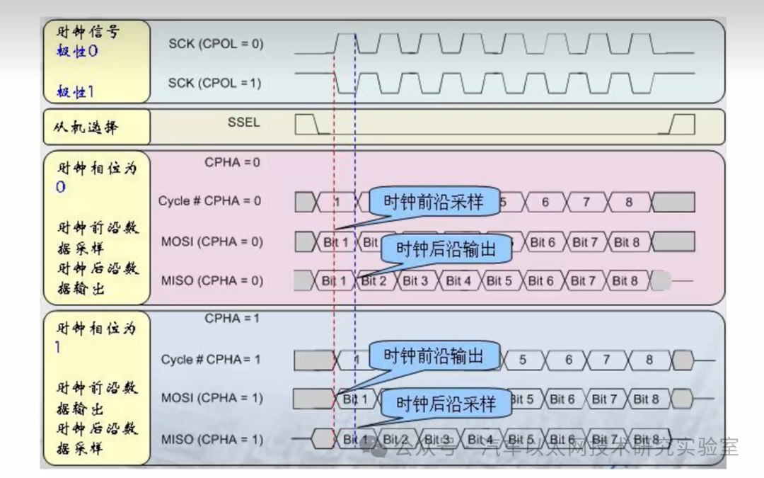
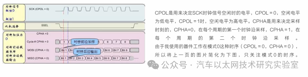
1. SPI (Serial Peripheral Interface) is a high-speed, full-duplex, synchronous communication bus that uses only four pins in its standard configuration.
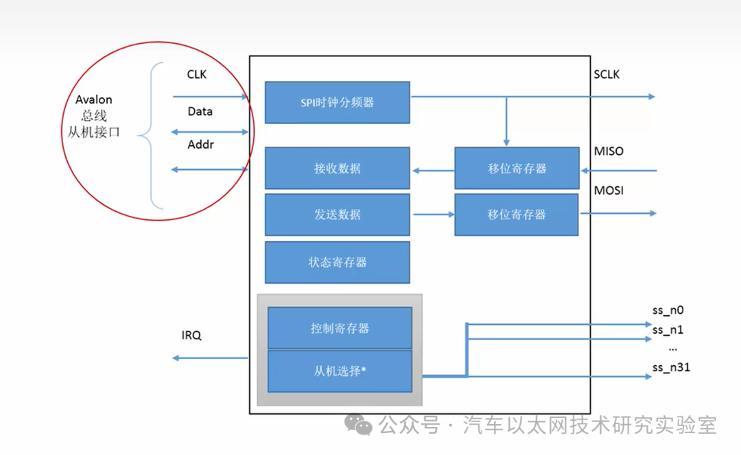
SPI IP core block diagram:
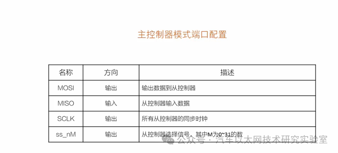

2. Register description of the SPI core
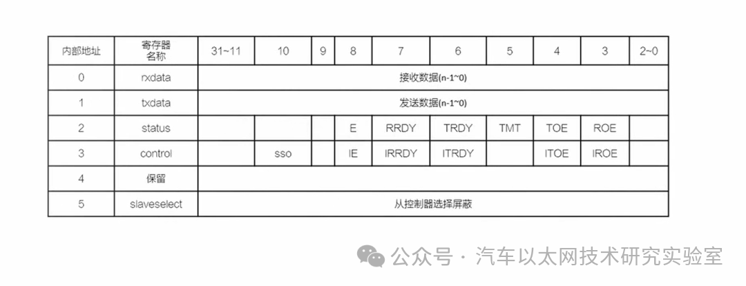
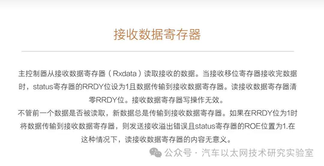
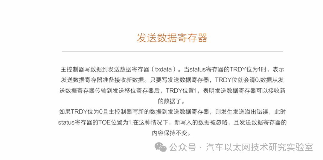
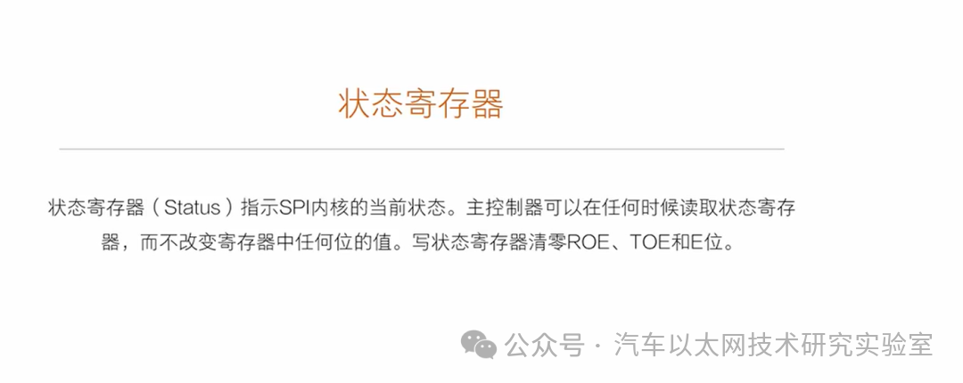
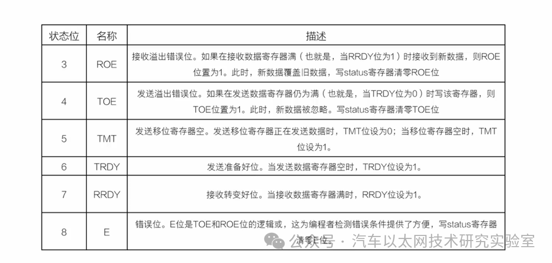

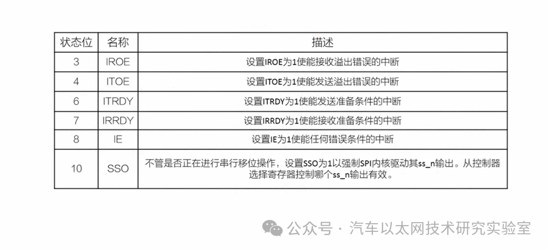

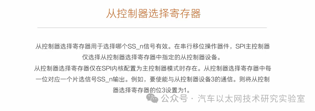
3. Configuring the SPI core
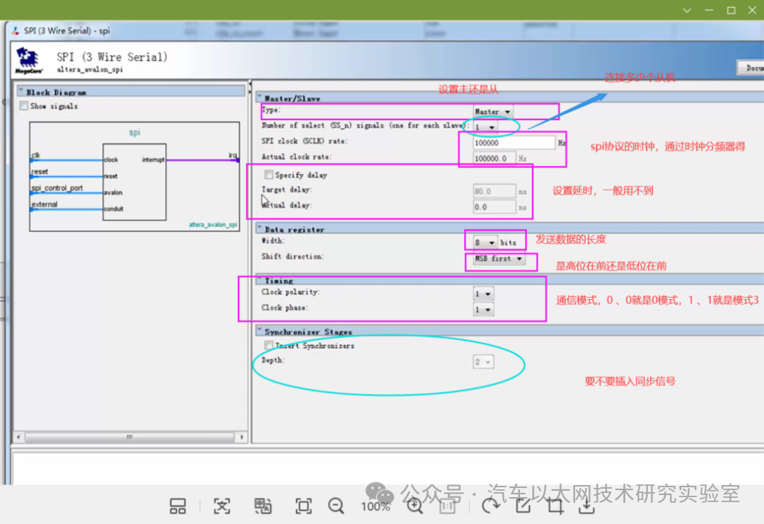
4. Programming the SPI core
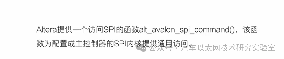
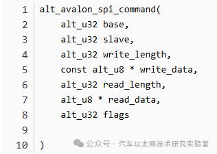
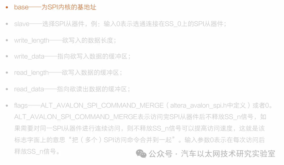
5. SD Card Interface
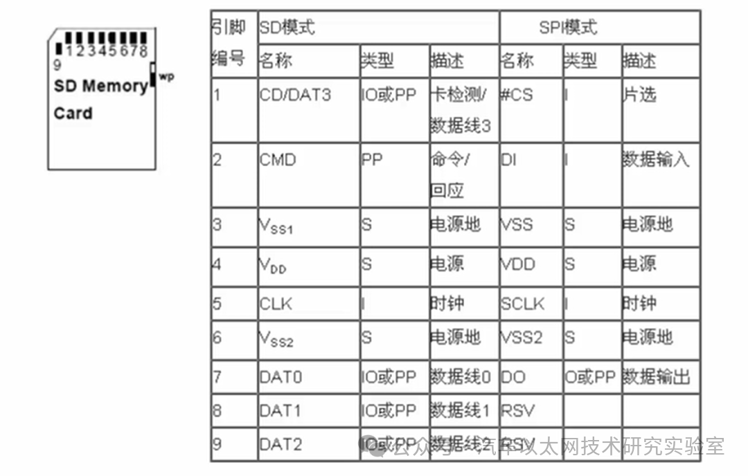
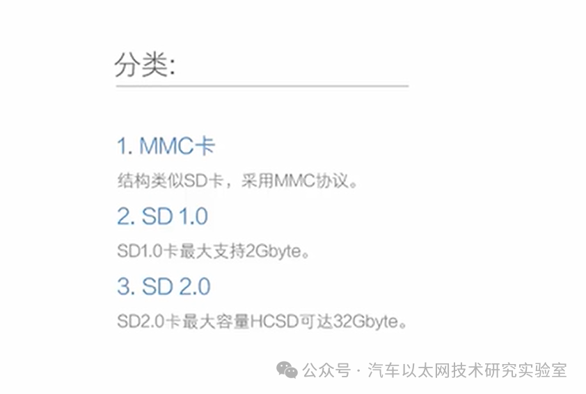
In SPI mode, the SD card acts as a slave device. The SPI controller issues commands, and upon receiving a command, the SD card responds with a response frame. For read and write operations, it continuously transmits data tokens and bulk data.
SD card command timing diagram:
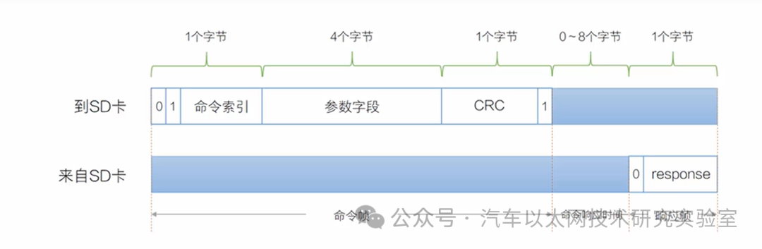
Master device sends command frame:
A command frame consists of 6 bytes, the first byte is the command starting with 01, followed by a 6-bit command index, the next 4 bytes are the parameter field, which can accommodate up to 32 bits of information. The last byte contains a 7-bit CRC (Cyclic Redundancy Check) code, with the last bit being the stop bit.
In SPI mode, the CRC check code is optional and is not used by default; it can be set to either 1 or 0. Even if the CRC feature is not used, the last byte must still be included to form the 6-byte frame format. The CRC code value can be calculated and added manually.
The SD card processes this command within a certain time (commonly referred to as command response time):
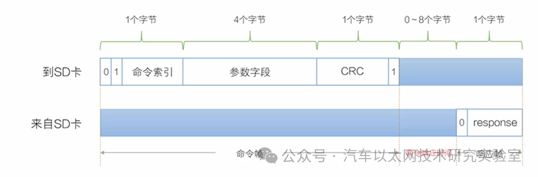
SD card responds with a response frame
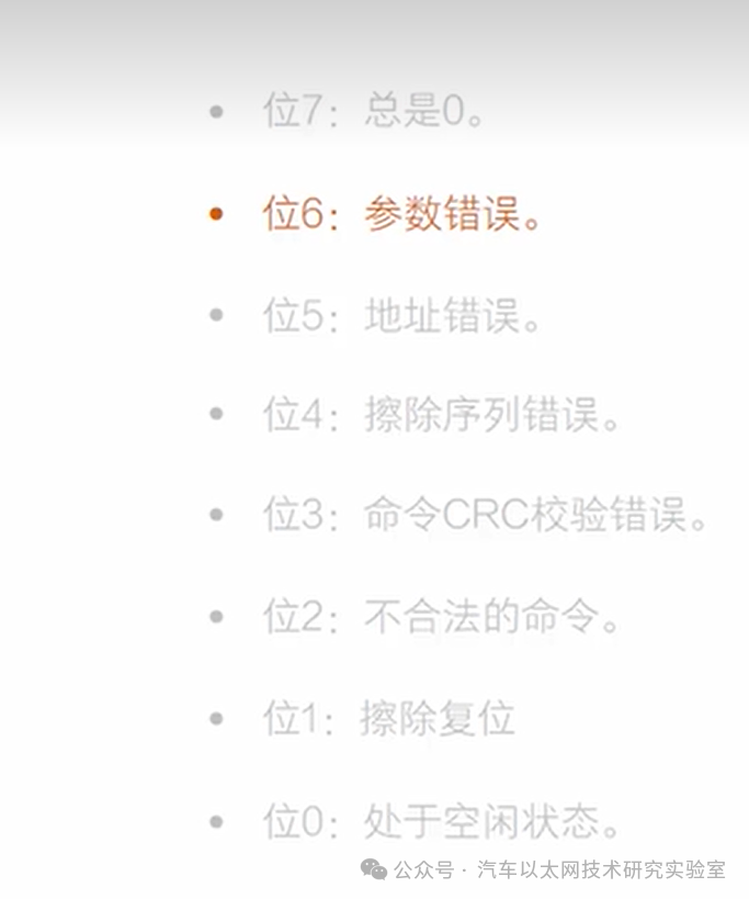
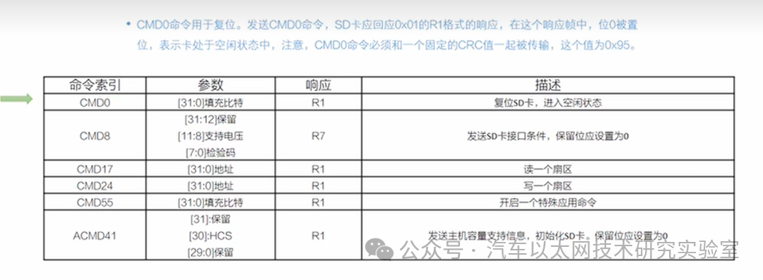
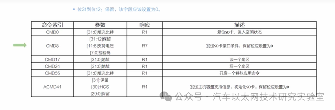
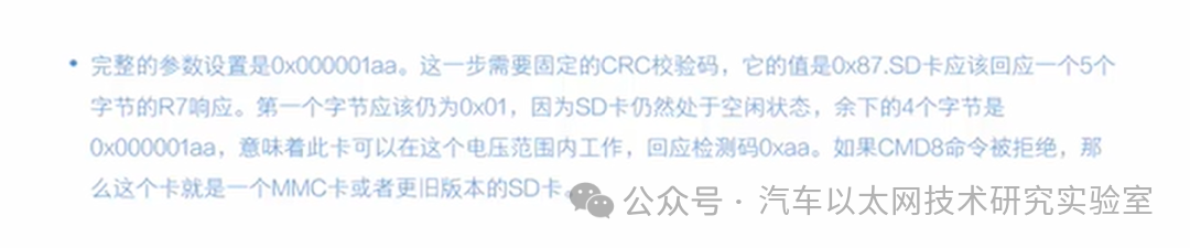
Most command expected responses are 0x00, indicating no error occurred. In our program, we also use the R7 format response, which contains 5 bytes; the first byte is the same as the R1 format, and the remaining 4 bytes return specific status information.


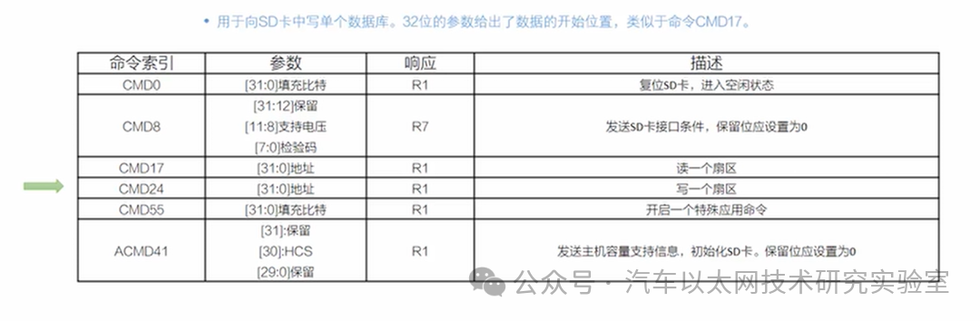
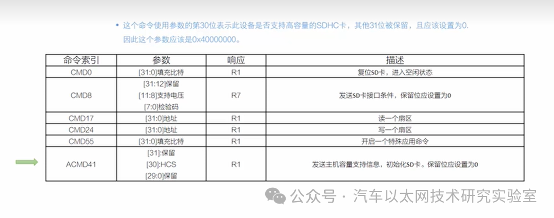
6. SD Timing
Resetting the SD card
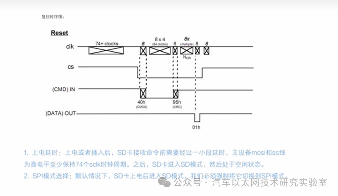
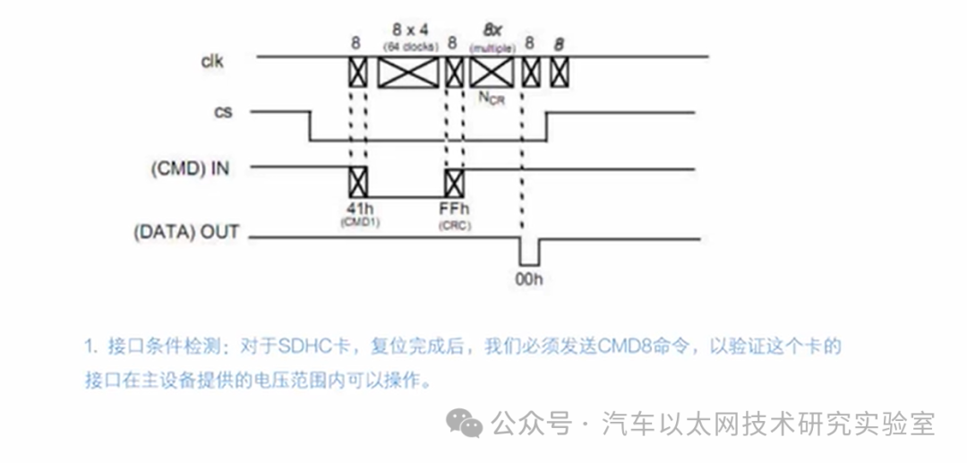
Initializing the SD card
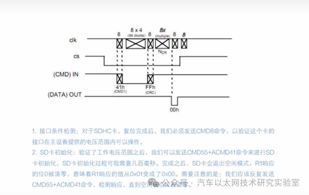
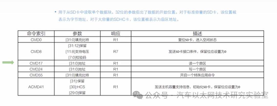
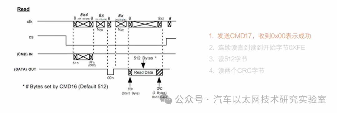
Reading a sector from the SD card
Data access for SRAM and SDRAM is done in bytes or words, whereas SD card data is accessed in blocks, with 512 bytes constituting one sector.
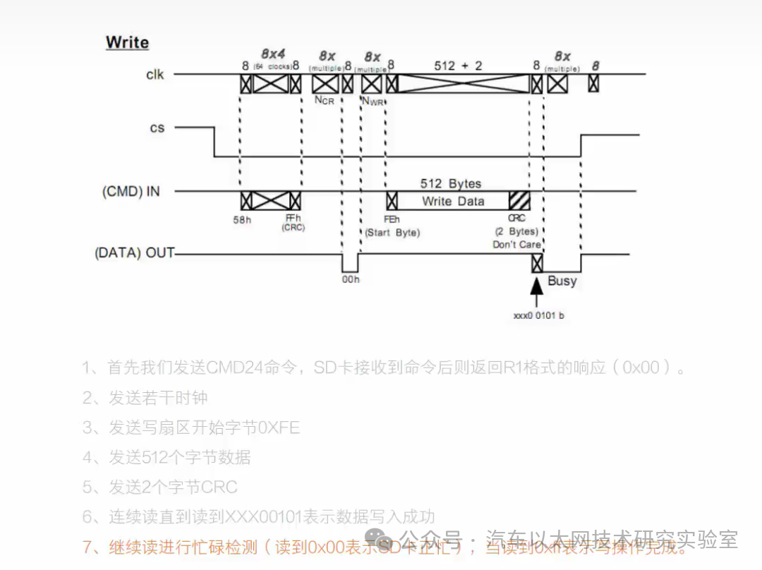
Writing a sector to the SD card



*Disclaimer: This article is original or forwarded by the author.If any party’s intellectual property rights are inadvertently infringed, please inform us for deletion.The above images and text are sourced from the internet; if there is any infringement, please contact us promptly, and we will delete it within 24 hours.The content of the article represents the author’s personal views,the Automotive Ethernet Technology Research Laboratory reprints it only to convey a different perspective and does not representthe Automotive Ethernet Technology Research Laboratory’s endorsement orsupport for this view. If there are any objections, please feel free to contact the Automotive Ethernet Technology Research Laboratory.
Original link:
https://blog.csdn.net/xzs520xzs/article/details/132148351