It is believed that the first task for anyone learning Arduino or other microcontrollers is to light up an LED, similar to the ‘Hello World’ program in C language. This time, we will also try to light up an LED using the GPIO of the Raspberry Pi.
1. Understanding Raspberry Pi B’s GPIO
GPIO (General-purpose input/output) is a term that refers to pins that can be controlled by the user through programming, similar to the P0—P3 pins of the 8051 microcontroller. The pins can serve as general-purpose input (GPI), general-purpose output (GPO), or both (GPIO), such as when used as a clock generator or chip select.
Since a pin can be used for input, output, or other special functions, there must be registers to select these functions. For input, it is possible to determine the high or low state of a pin by reading a certain register; for output, writing to a register can set the pin to output high or low; and for other special functions, there are separate registers to control them.
For beginners, understanding GPIO can be seen as external pins brought out from the chip, with at least two functions (input and output). How to explain output? For example, if we connect an LED, the CPU needs to control a pin to become high to provide + power to the LED, which is output. How to explain input? For example, if we connect an infrared human sensor, the CPU needs to detect the state from a pin. If it senses a person, that pin will become high, which is input.
The multiplexing of GPIO refers to certain pins that, besides functioning as regular input and output, also have special functional roles. For example, they can be used for JTAG debugging, serial TX, RX, etc. However, each pin can only be used for one function at a time; multiplexing does not mean a pin can do both input and output simultaneously.
This means that before using GPIO, we need to set the corresponding mode for the pin we want to use, and it will revert to its initial MODE state after a reboot. Each pin set to a different mode has different functions. Some pins are fixed, such as 3.3V, 5.5V, and GND, which cannot be used as operable GPIO.
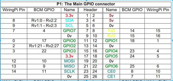
First, let’s take a look at the GPIO of Raspberry Pi B, which has 26 pins.
Raspberry Pi pins can be numbered in various ways: essentially, there is not much difference; only the corresponding pin numbers differ based on the numbering scheme.
Assuming we are using pin 15 of the P1 numbering scheme (15 in the Header column), it is called GPIO3 (the name may vary). If we use the BCM numbering scheme, it is pin 22. If we use WiringPi, it is pin 3. Using different numbering schemes, the pin numbers may vary. As long as you refer to the correct table, there should be no issues.
The actual board is labeled using the P1 numbering scheme. In Python GPIO, this is the BOARD mode.
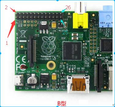
Unless otherwise specified, we will default to the P1 numbering scheme. The numbering goes from 1 to 26 from top to bottom, left to right (please rotate the image I provided 90 degrees clockwise before counting QAQ).
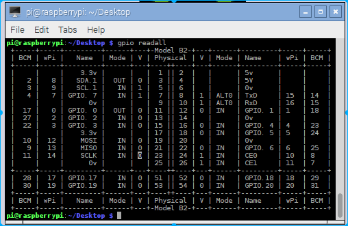
By executing #gpio readall, you can accurately obtain your board’s GPIO information.
First, let’s take a look at the initial mode of each PIN. Here we will first look at the results. Later, we will provide the source code for reading using Python.
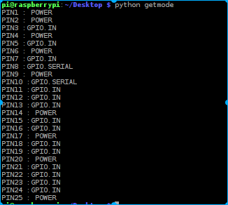
From here, we can see that PIN8 and PIN10 are defaulted to serial mode. In the previous section, we did not set the mode for serial debugging, but it still works because the board defaults to serial mode for pins 8 and 10 after startup. Among the other pins, 1, 2, 4, 6, 9, 14, 17, 20, and 25 are power pins, either 3.3V, 5.5V, or GND. The others default to GPIO.IN, all in input mode, and to light up the LED, we definitely need to set one pin to OUT mode.
2. Directly Lighting Up an LED
From the table, we can see that PIN1 is the positive terminal for the 3.3V power supply, and PIN6 is 0V, which is the negative terminal (GND). If we connect an LED, will it light up automatically? That would be clever! That’s how it’s connected, but for safety, it’s better to connect a resistor of around 300 ohms.
3.3/300=0.011A=11mA. This is relatively safe. I won’t elaborate on high school physics here.
Required materials:
1. Breadboard (to facilitate wiring without manual connections)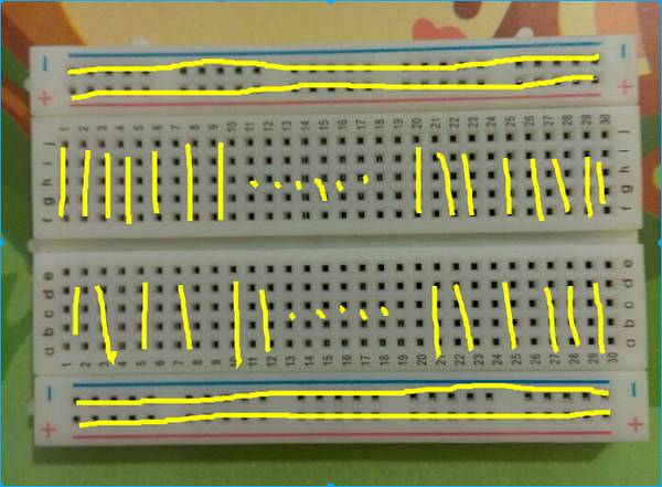 The holes in the middle of the breadboard are connected vertically, but not between pairs. The edge holes are connected horizontally, but not between pairs.
2. Two male-to-female Dupont wires
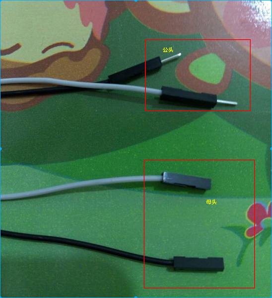 It is easy to distinguish between male and female. Male is the one that plugs into others, and female is the one that is plugged into (self-reflect for two minutes). Of course, Dupont wires also come in male-to-male and female-to-female types, and since they are cheap, it’s okay to buy a few extra.
3. One LED (reference voltage 3.0-3.2V) with a current of 5-20mA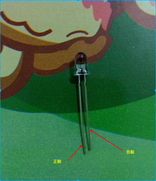 Note the polarity of the LED. How to distinguish? First: the longer pin is positive, and the shorter pin is negative, as shown in the image. Second: look inside the LED; it is divided into two parts. The larger part is connected to the negative, and the smaller part is connected to the positive.
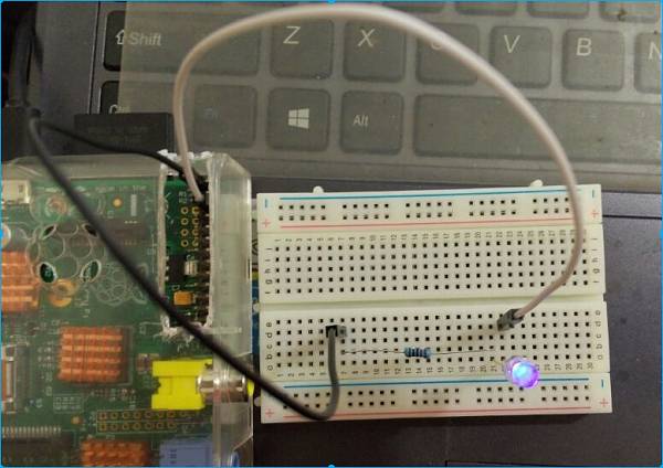
4. One resistor of around 300 ohms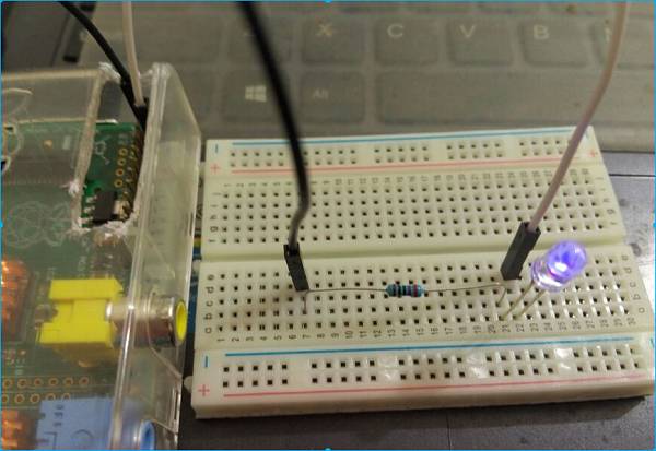 There’s nothing much to say about this. The wiring is: PIN1 (3.3V positive) ——– resistor —— LED positive ——– LED negative ——— PIN6 (GND negative). The LED will light up.

3. Programming to Control the LED
Common libraries used to operate Raspberry Pi GPIO include two: one is the Python library RPi.GPIO (https://pypi.python.org/pypi/RPi.GPIO), and the other is the C language library wiringPi (http://wiringpi.com/).
1. Using RPi.GPIO
The complete version of the default installed IMG comes with the RPi.GPIO library and Python environment, so we do not need to install it. If installation is needed, use #sudo apt-get update to install Python, and #sudo apt-get install python to install pip, then use pip to install RPi.GPIO: #sudo pip install rpi.gpio. This time we need to modify the wiring scheme above. Since we want to program a pin, we cannot use the power pins. We choose to connect to PIN3, keeping the rest unchanged. Just connect the wire that was originally connected to PIN1 to PIN3. We won’t provide an image here. The connection is: PIN3 positive ——– resistor —— LED positive ——– LED negative ——— PIN6 negative. Python syntax is simple and easy to learn.
Edit a text file and write:
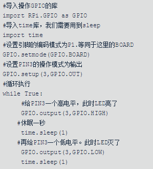
With the above code, you will see your LED blinking once every second. (This script does not exit and does not clean up resources upon exit). You can also try modifying the sleep time; for example, time.sleep(0.2) will make the blinking frequency faster. Meanwhile, let’s check the mode of PIN3.
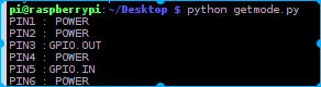
We find that it has already changed to GPIO.OUT. This is the effect of GPIO.setup(3, GPIO.OUT) in our script.
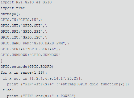
The Getmode.py script is as follows. No further explanation is needed (power pins cannot be operated, which will cause exceptions).
2. Using wiringPi for operations
Similarly, we will perform the same tasks using the C language wiringPi.
Download the wiringPi library (I won’t explain the installation of git; the default complete image comes with it). Clone it from git:
#git clone git://git.drogon.net/wiringPi#cd wiringPi#./build
Wait for the compilation to complete; the Raspberry Pi B CPU at 700MHz is relatively slow, so it may take a while.
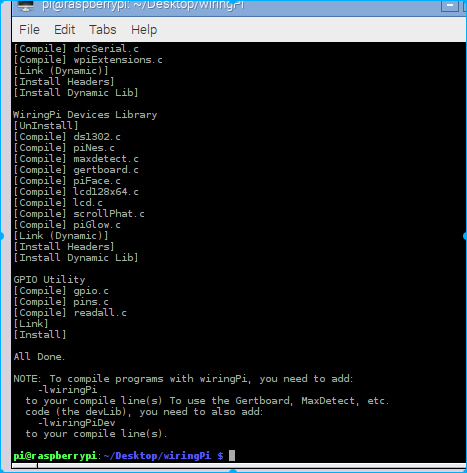
After compilation, it will automatically install into the /usr/local/lib directory. You only need to use the header file and lib. If your system does not have this directory, refer to the INSTALL file in the wiringPi directory for solutions. We create a new file called led.c.
#include <wiringPi.h>
#include <unistd.h>
#include <stdbool.h>
int main()
{
// Initialize environment
wiringPiSetup();
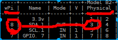
// Set PIN3 to output mode, corresponding to wiringPi, the previous icon number should be 8. This is particularly important.
pinMode(8, OUTPUT);
while(true)
{
sleep(1);
// Write high
digitalWrite(8, HIGH);
sleep(1);
// Write low
digitalWrite(8, LOW);
}
}It is important to note that the numbering is no longer 3, but 8, because we are using wiringPi.
Start compiling this file: #gcc -o led led.c -lwiringPi, which means to create a binary file named led from led.c, linking using the wiringPi development library (the basic library is linked by default, so there’s no need to specify it). If you do not use -lwiringPi, it will prompt a linking error with undefined references.
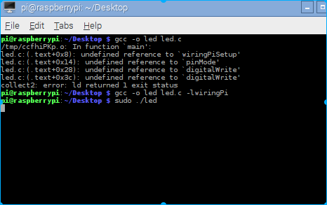
After compiling, execute it with administrator privileges: #sudo ./led, and you will see the LED blinking once every second.
What device will we play with next? A buzzer? An infrared human sensor? A camera? Or after the infrared sensor detects a person, the buzzer will sound an alarm?
Or an internet camera, with Raspberry Pi as a client, transmitting home video to your phone over the internet, allowing you to see the situation at home on your phone? We could continue to add motion detection to the camera. When abnormal motion is detected, the buzzer will sound an alarm and report to the external cloud?
Combining a buzzer, human sensor, camera, internet cloud terminal, and mobile phone terminal creates a small security monitoring system.
Visit Kanxue for testing: http://ce.kanxue.com
Kanxue Forum: http://bbs.pediy.com/

—– WeChat ID: ikanxue —–
Kanxue • Security has been focusing on security for 16 years, providing professional services!