

【Tip】Click the blue text below the titleElectrician HomeFollowFor business cooperation, please contact QQ: 2226701662
For more exciting consultations, please follow Electrician 365 (diangong365) Electrician Home QQ group:① Group: 468193845 ② Group: 522898769
1. Overview
The human-machine interface is a bridge for two-way communication between operators and machinery, allowing users to freely combine text, buttons, graphics, numbers, etc., to process or monitor management and respond to potentially changing information on a multifunctional display screen. With the rapid development of machinery, the previous operating interfaces required skilled operators to operate, which was difficult and could not improve work efficiency. However, using a human-machine interface can clearly indicate and inform operators of the current status of the machinery, making operations simple and vivid, and reducing operational errors, allowing even beginners to easily operate the entire machinery.
Using a human-machine interface can also standardize and simplify machine wiring while reducing the number of I/O points required by the PLC controller, lowering production costs. Additionally, due to the miniaturization and high performance of panel controls, the overall added value of the equipment is relatively improved.
The touch screen, as a new type of human-machine interface, has attracted attention since its inception. Its simplicity, powerful functions, and excellent stability make it very suitable for use in industrial environments, and it can even be used in daily life, with a wide range of applications such as: automated parking equipment, automatic car washes, crane lift control, production line monitoring, etc., and can even be used for smart building management, conference room sound and light control, temperature adjustment…
1.1 Basic Structure and Working Principle of Touch Screens
According to different working principles and transmission media, they can be divided into:
Resistive
Capacitive
Infrared
Surface Acoustic Wave
(1) The main structure of the resistive touch screen
It consists of a multi-layer transparent film that matches the surface of the display screen.
Base layer: Reinforced glass or hard plastic flat plate, coated with a layer of conductive resistance layer (such as indium tin oxide – ITO).
Surface layer: A smooth, scratch-resistant plastic layer that has been surface-hardened, with a conductive layer coated on its inner surface.
Isolation points: Transparent plastic particles smaller than 0.001″.
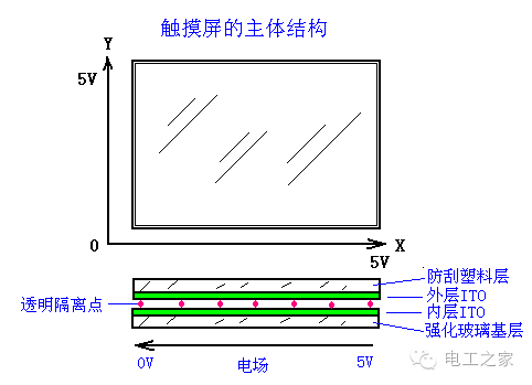
(2) Working Process
DC voltage is applied in the X and Y directions on the inner layer ITO, creating an electric field of +5V to 0V in both X and Y directions, with the potential at each point distributed linearly according to a gradient.
When a finger or hard object presses the touch screen, a depression occurs at the touch point, causing the outer layer’s inner surface ITO coating to contact the base layer’s ITO layer. At this point, the outer layer ITO’s potential changes from the original 0V to a non-zero value. The controller applies voltage to the X and Y axes in turn and measures the height of the outer layer’s potential. After A/D conversion and comparison with the 5V voltage, the coordinates of the contact point can be calculated, and the corresponding program can be executed through mouse-like operations.
(3) Classification of Resistive Touch Screens
4-wire – the outer layer ITO is powered, and the inner layer acts as the detection layer.
5-wire – the inner layer ITO is powered, and the outer layer acts as the detection layer.
2. Touch Screen and Human-Machine Interface
The touch screen is just a transparent positioning device and must work in conjunction with controllers, CPUs, display controllers, display panels, etc., to function properly.
Industrial control touch screens (human-machine interfaces) combine the above devices into a standalone flat-panel display used in conjunction with PLCs. Their protective capabilities and reliability are relatively high.
3. Selection of Human-Machine Interfaces
Pay attention to the power supply voltage used by the human-machine interface, which usually has AC220V and DC24V.
Ensure compatibility with the PLC types that can work with the human-machine interface.
Determine the size, color, number of windows, animation functions, report printing functions, interface types, etc., based on usage needs.
Check if special communication cables need to be selected.
2. Introduction to WinView Human-Machine Interface MT506
The MT500 series touch screen from Taiwan Weilan Company (WinView) is specifically designed for PLC applications and can directly connect with most mainstream PLCs. Like PLCs, it is an industrial product designed based on factory application environments, with high reliability and stable operation in industrial environments ranging from 0℃ to 45℃. The front panel has an IP65 protection level (splash-proof), and the dimensions are 204×150×48mm, suitable for installation on the front panel of electrical control cabinets.
It features a 5.7″ LCD display panel, 256 colors, with a resolution of 320×240. The touch panel is a 4-wire resistive type and is powered by a DC24V power supply, with a maximum of 1999 windows and up to 6 pop-up windows that can be opened simultaneously.
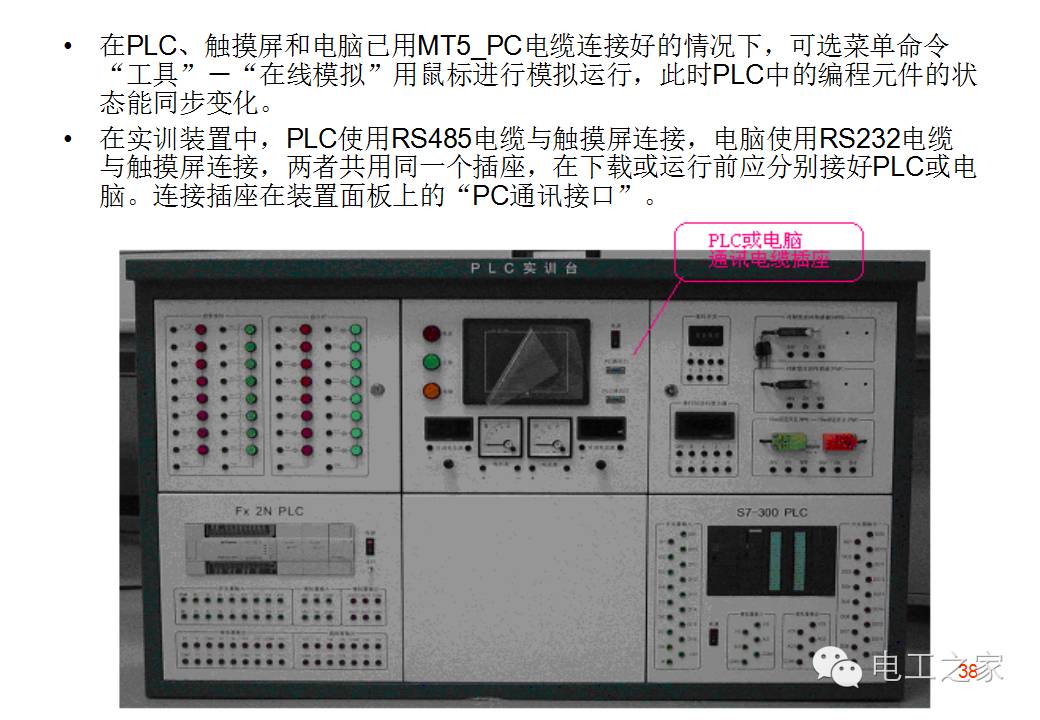
The MT506 has RS232C and RS485 interfaces and can connect to PLC or PC via communication cables. The cable length should not exceed 150m when using RS485 and 15m when using RS232C.
The PLC/PC [RS-485/RS-232] port on the MT500 is generally connected to a computer. Since the PC [RS-232] and PLC [RS-485] share a COM port, it is recommended to use the MT5_PC cable to split the shared COM port into two independent COM ports. The PLC [RS-232] port on the MT500 can be connected to the PLC. Also, ensure that the DIP switch is set to the “OFF” position (this is the default setting when the touch screen leaves the factory).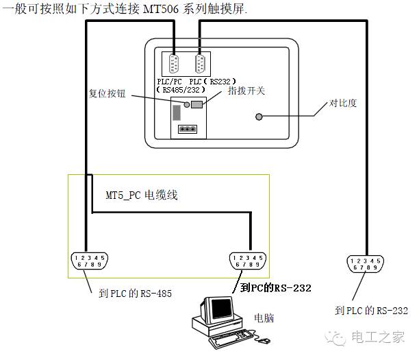
The DIP switch on the back of the MT500 can set the starting mode when the touch screen is powered on, with the default setting being online operation (application program) mode.
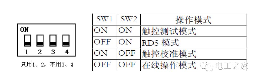
Touch Panel Calibration:
Since each touch screen analog resistor is different, the touch panel should be calibrated when the CPU board or touch panel is replaced. The wizard on the touch screen can guide you through the entire touch panel calibration process.
Touch Panel Testing:
In this mode, when you touch the screen, a “+” will be displayed at the same position where you pressed. This tests the accuracy of the touch panel.
RDS Mode:
In this mode, the touch screen is always waiting for commands from Easy Manager (running on PC). After self-check, the screen will display the system’s internal information. To upgrade BootROM, the touch screen must first switch to RDS mode.
Online Operation:
After entering this mode, if a project is loaded in the touch screen, the initial window of that project will be displayed. If there is no project, the system will not run correctly. In this case, you must switch the system to RDS mode, download a complete project, and then return to online operation mode.
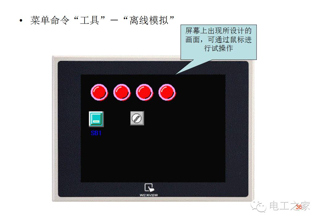
3. Steps for Touch Screen Program Production
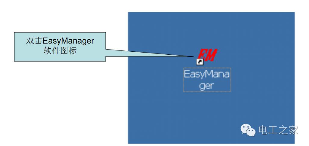
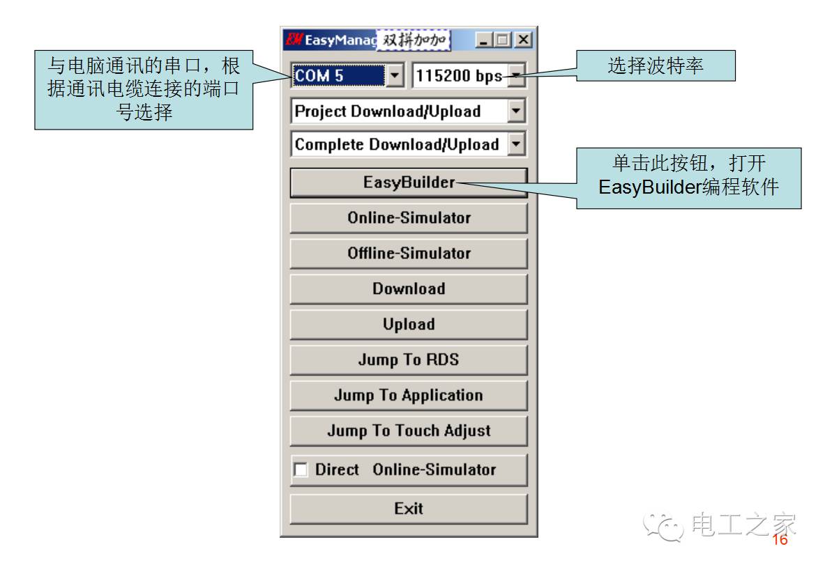
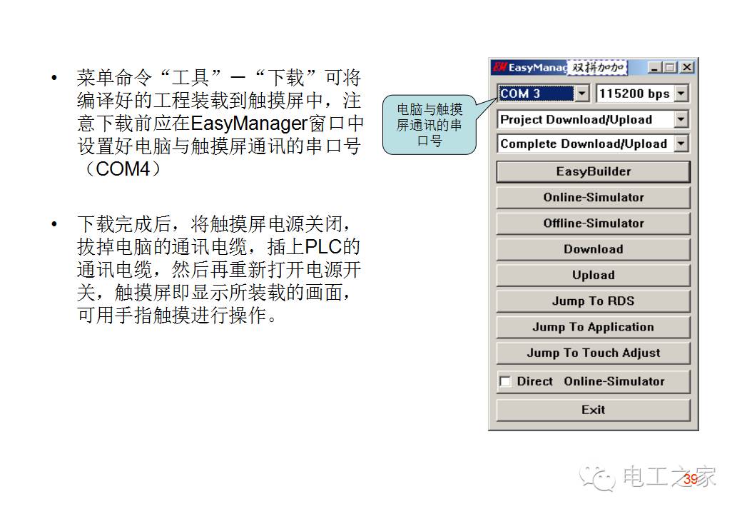
1. Open EasyManager
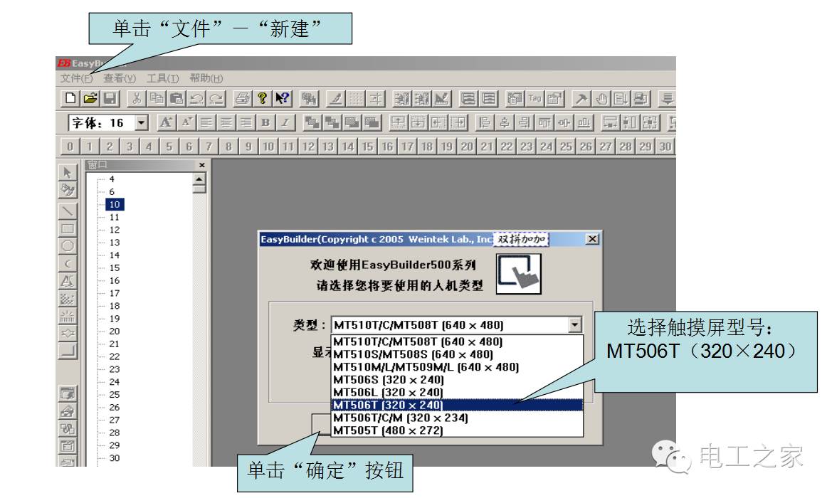
2. Create a new project
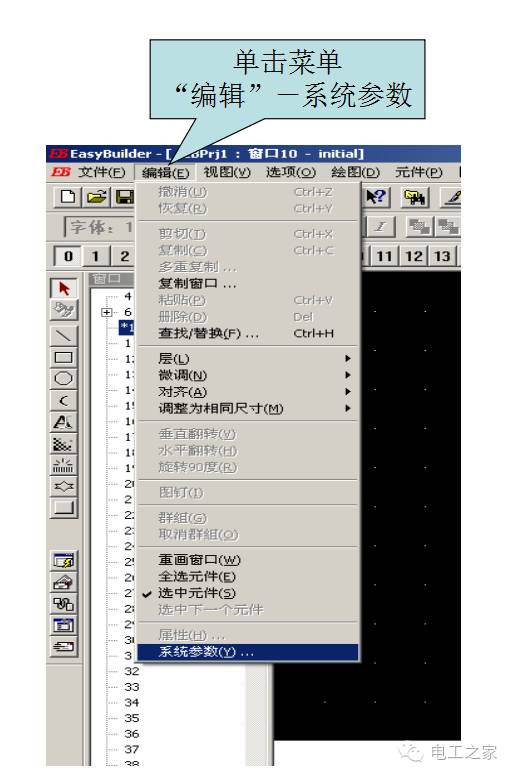
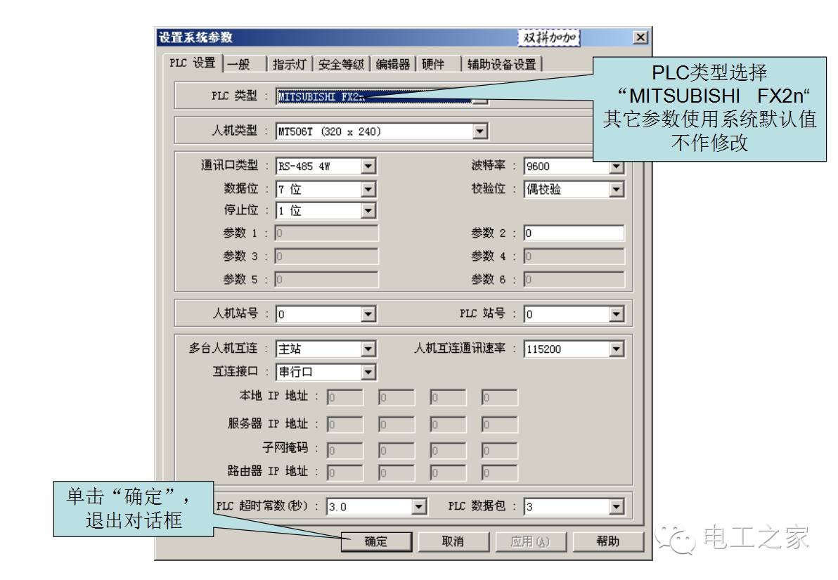
3. Set system parameters
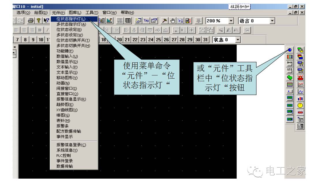
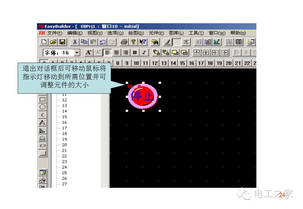
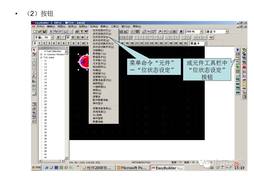
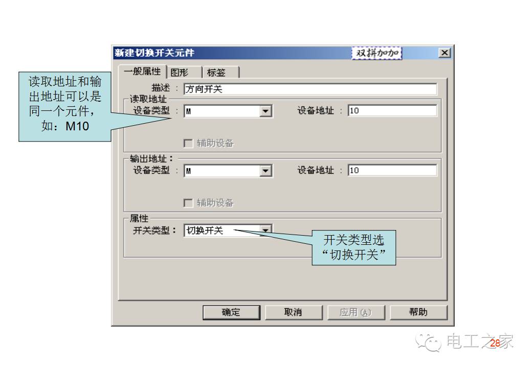
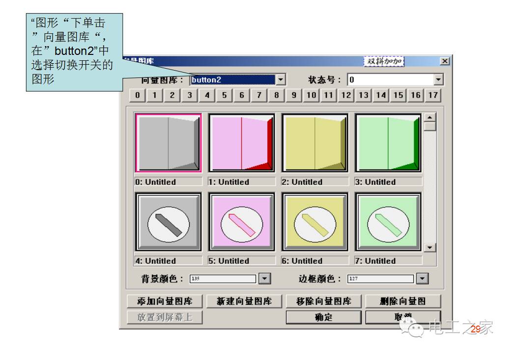
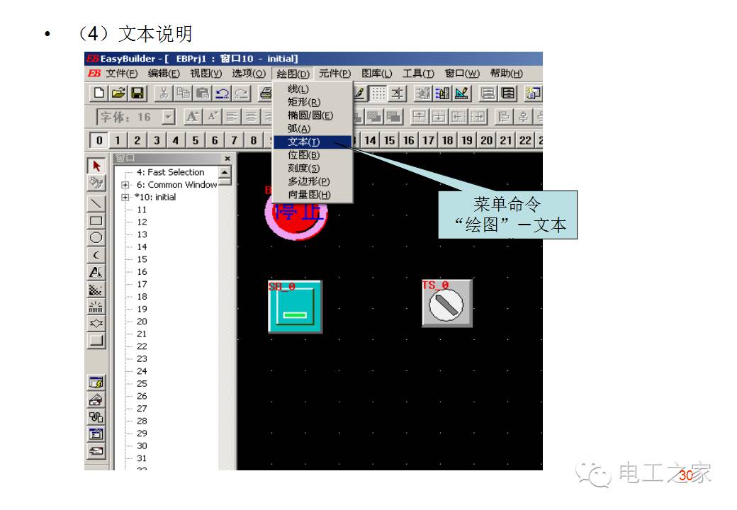
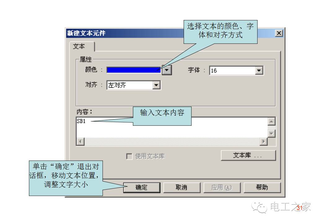
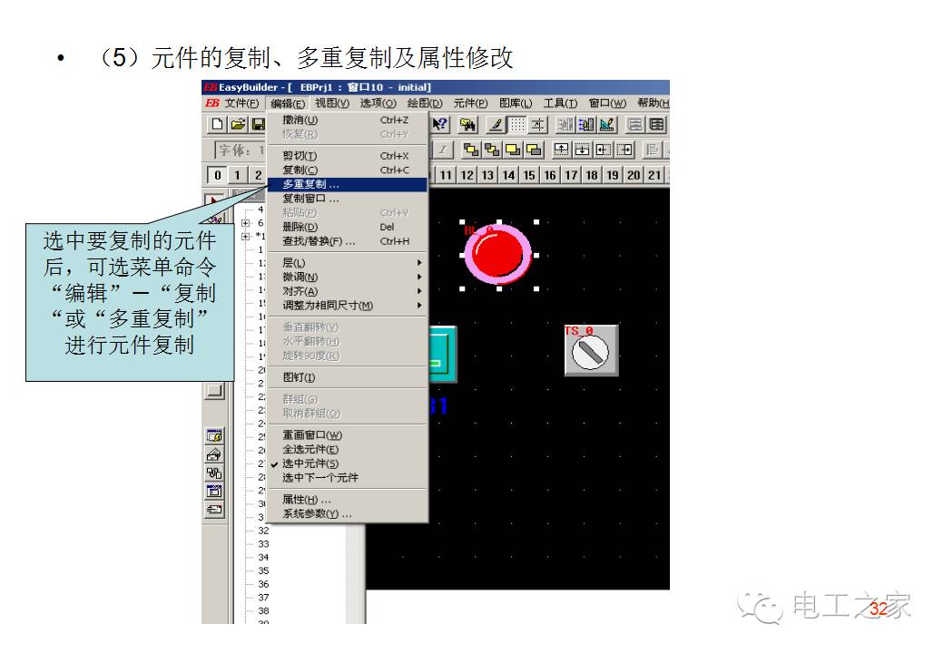
4. Add components in the blank window
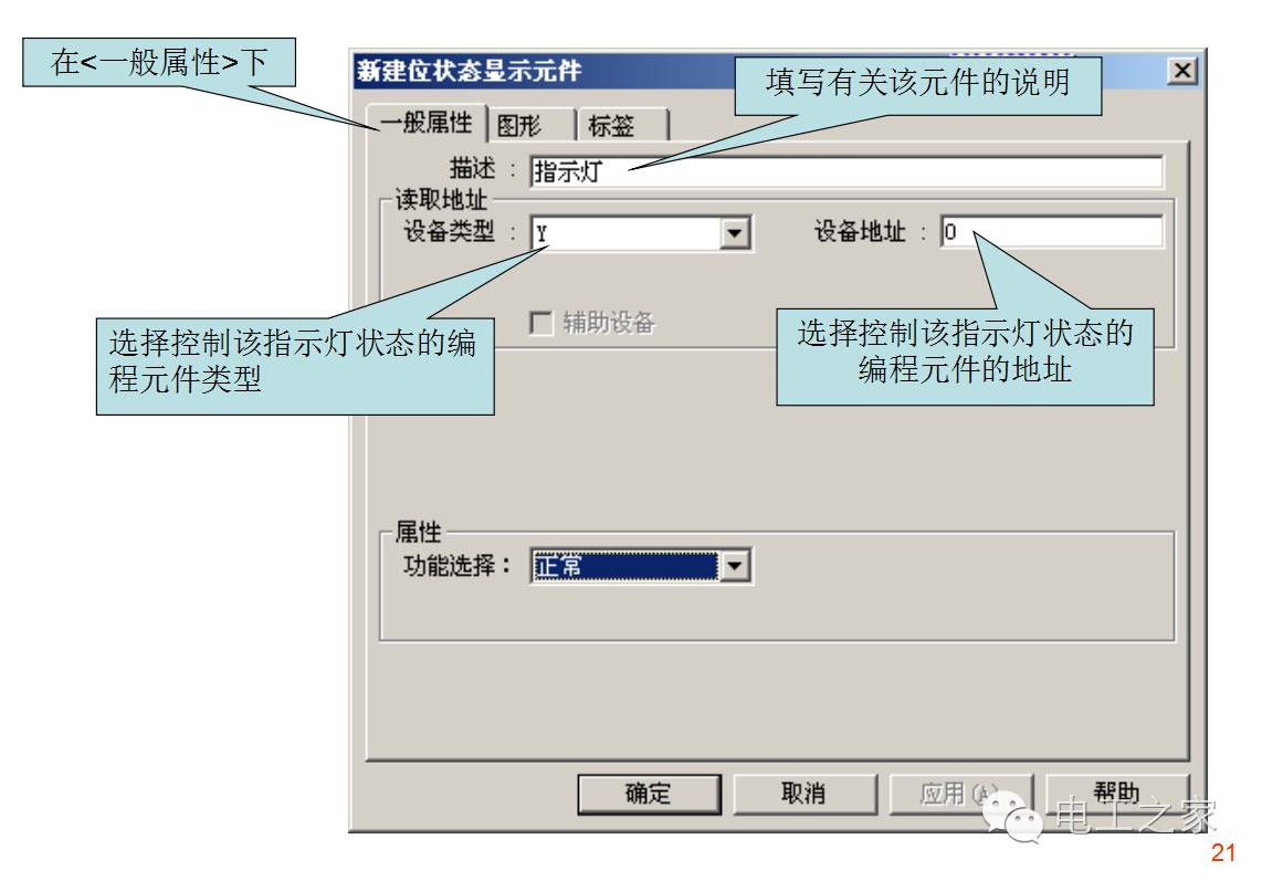
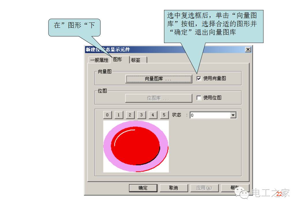
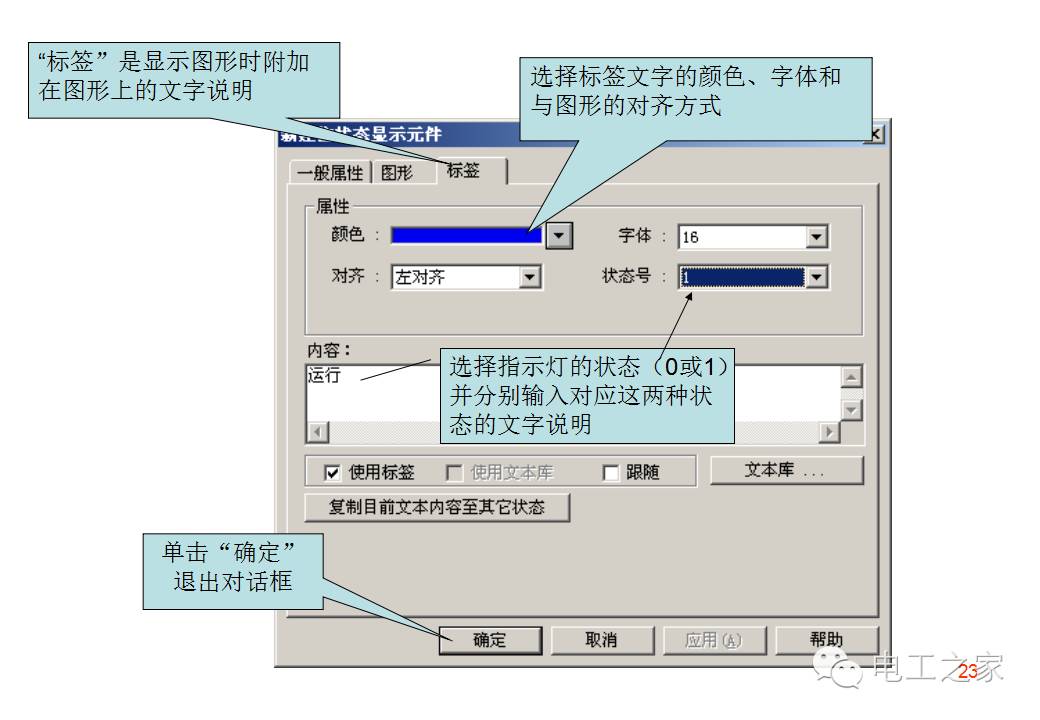
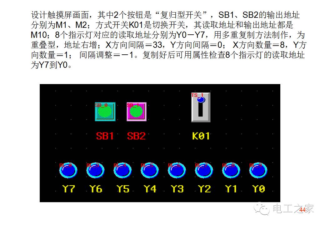
(1) Status indicator light
To get more video materials, please follow Electrician 365 (diangong365) or long press the image to recognize the QR code to follow. After following, type “Electrician” in the dialog box to get the link…