Introduction
It’s been a while since I posted an article, haha. This time, I’m sharing a complete guide on building a home server from scratch. Starting from zero, we will use idle hardware at home to create a fully functional server. The content includes but is not limited to: 1. Enhancing network functionality 2. Building a server 3. Cluster processing 4. Docker container management 5. Multimedia services.
Without further ado, let’s get started!
Preparation
1. FriendlyArm’s ZeroPi (any Linux development board can be used, such as Raspberry Pi)
2. A 32G Class 10 memory card (at least 8G, the more the better)
3. A 5v2A power adapter; I used the USB output from my computer as ZeroPi requires very low current.
4. A regular home router; mine is Redmi AX5.
5. Some basic knowledge of computer networks.
Why Do We Need a Bypass Router?
Quick fact: Most router firmware on the market is a modified version of OpenWrt.
Reasons:
1. Regular home routers have limited functionality and do not support many features, such as SMB, IPv6, multicast, and disabling NAT. For enterprise or government clients requiring VPN for remote network access, many features cannot be installed or selected themselves.
2. Regular home routers support certain functions, but their performance is limited. Once complex functions are enabled, the router may not be able to perform its duties, leading to packet loss and disconnections. Yes, I’m referring to certain low-quality routers that frequently malfunction. At this point, other hardware is needed to handle higher-level tasks, reducing the router’s burden and ensuring a smooth and stable home network.
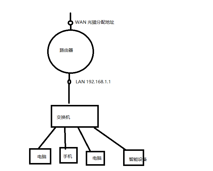
Below is a common interface diagram of home routers; in reality, there are only two physical interfaces (the LAN ports are essentially a switch).
The corresponding network topology is as follows:
What is a Bypass Router?
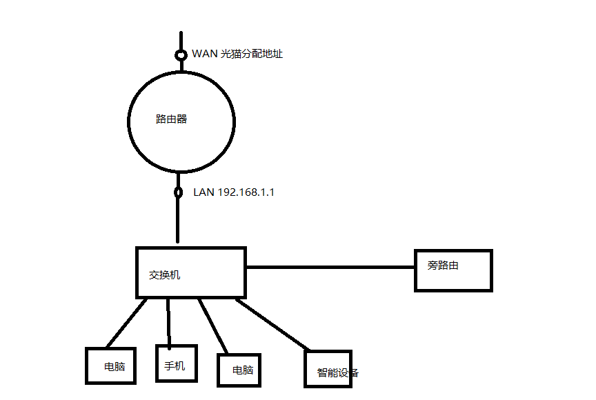
Based on the above diagram, we have a general structure of a home network. Now we need to set up a proxy in the middle to intercept traffic originally going from the user to the router. After “processing” through this proxy, the traffic can be sent directly to the home router. This way, the home router only needs to focus on traditional routing and switching functions without handling transport or application layer data, ensuring a low load on the home router and enhanced network functionality.
Thus, we propose a new network structure with the following physical structure:
The actual data flow is as follows:
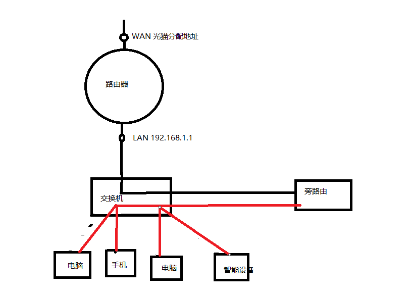
The reason it is called a bypass router is that it sits aside, isn’t that a vivid description?
Deployment Process
Preparing OpenWrt
Manual Download
Visit the official OpenWrt website at https://openwrt.org/toh/start, and find your device in the provided list of supported devices; common devices are listed here.
The downside is that only some common software is included. If your device only has a snapshot version of the image, that can be unfortunate, as common software may not be included, and SSH and LuCI may not be enabled, requiring manual compilation.
Self-compiling
Compilation Environment: Ubuntu 20.04 LTS
I am using the Linux subsystem on Windows, which can be installed directly from the Microsoft Store.
Open the terminal and input the command:
sudo apt update && sudo apt upgrade -yThis updates the software source information and all software packages.
Install dependencies:
<span>sudo apt-get -y install build-essential asciidoc binutils bzip2 gawk gettext git libncurses5-dev libz-dev patch python3 python2.7 unzip zlib1g-dev lib32gcc1 libc6-dev-i386 subversion flex uglifyjs git-core gcc-multilib p7zip p7zip-full msmtp libssl-dev texinfo libglib2.0-dev xmlto qemu-utils upx libelf-dev autoconf automake libtool autopoint device-tree-compiler g++-multilib antlr3 gperf wget curl swig rsync</span>
Clone the official OpenWrt repository:
<span>git clone https://github.com/openwrt/openwrt</span>
Enter the folder and download the required dependencies (ensure a good internet connection during this process):
cd openwrt # enter the folder ./scripts/feeds update -a # update dependency directory ./scripts/feeds install -a # install dependencies make menuconfig # open the compilation configuration menuThe interface looks like this. In the target system, subtarget, and targetProfile, find the corresponding hardware.
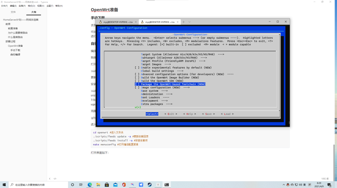
In Base System, use the space bar to select dnsmasq-full, remove dnsmasq (make sure to remove it, or it will cause compilation failure), select LuCI-collection-LuCI (Web management interface), and you can add other software packages as needed.
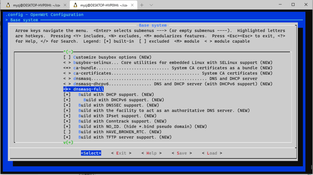
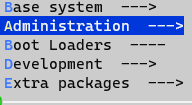
I added aria and smb, but you can skip this and compile directly; you can install them later. Press ESC twice to save the configuration, then input in the terminal:
make -j8 download V=sThis will download some external libraries.
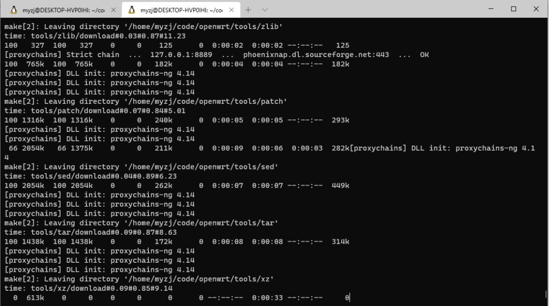
Once downloaded, enter:
make -j16 V=s -jThe number at the end is the thread count; V=s represents the view mode, which is optional but helpful for troubleshooting.
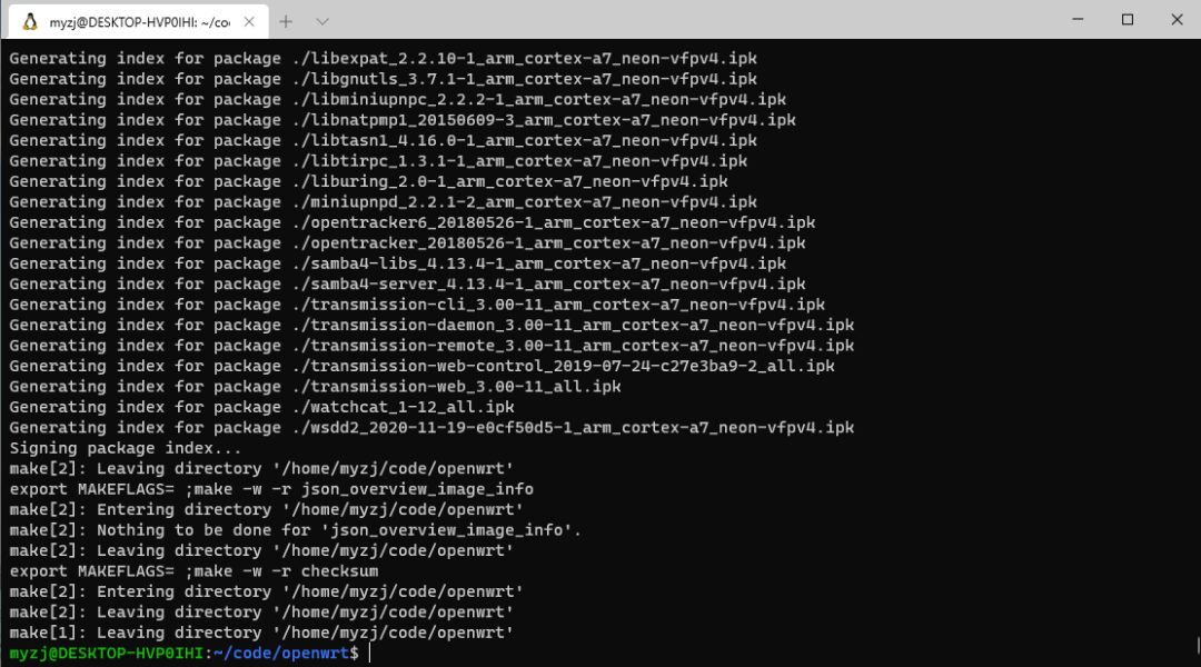
If compilation is successful, the image will be located at<span>~/code/openwrt/bin/targets/sunxi/cortexa7</span>. Depending on the hardware, the generation path may vary. The main content obtained is as follows:
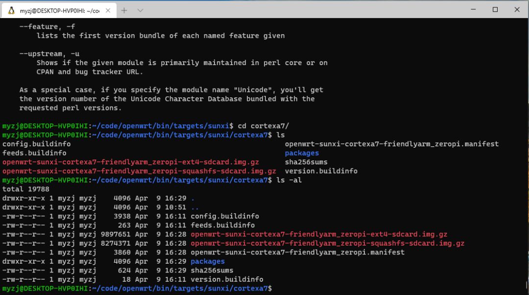
We will use<span>openwrt-sunxi-cortexa7-friendlyarm_zeropi-ext4-sdcard.img.gz</span> to flash onto the memory card.
Flashing
Use Etcher to flash the image, as shown below:

Once flashing is successful, insert the memory card into the development board!
First Boot
First, connect the development board directly to the computer with an Ethernet cable, enter 192.168.1.1 in the browser to open the web management interface, and log in using root (no password).
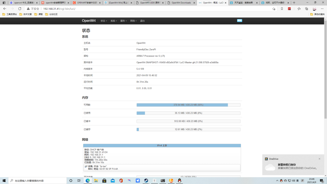
Check the GateWayPorts option in System-Administration and set the root user password.
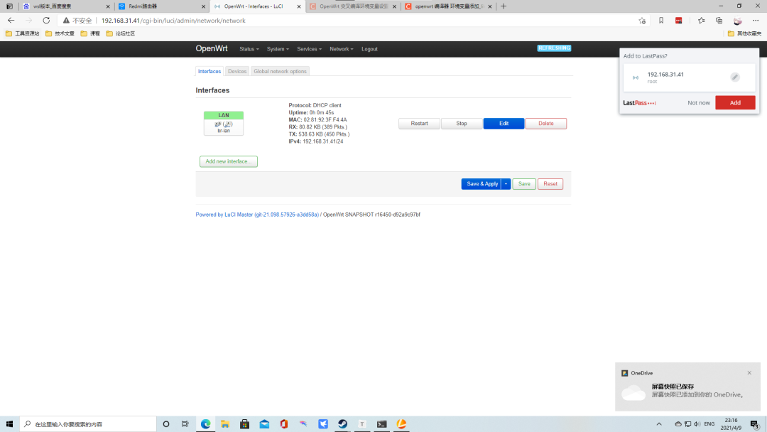
After setting a custom password, go to Network-Interface, click Edit, and change the interface protocol to DHCPClient. Then power off the development board, connect the Ethernet cable to the home router, power it back on, and it will receive an IP address normally. You can then access the web management interface using the IP address assigned by the home router. At this point, you can enable commonly used features like Adblock, aria, etc.
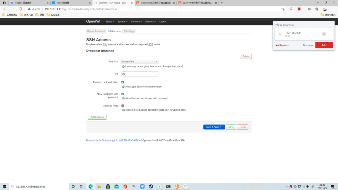
You can also enable SSH now.
Software packages can be installed here; it provides a very useful software search function.
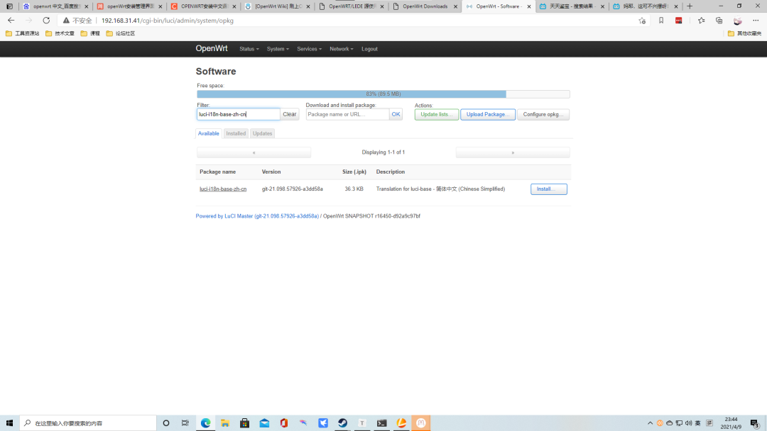
If your home network is poor, you can change the source of opkg. For instructions on changing the source, refer to this tutorial: https://mirrors.tuna.tsinghua.edu.cn/help/openwrt/.
Main Router Configuration
In the bypass router’s backend, go to Network-Interface, click Edit, and change the interface protocol to a static address, such as 192.168.31.2, and change the default gateway to 192.168.31.1.
Access the backend of the main router; mine is a Xiaomi router, and find the DHCP-related configuration as shown in the image below:
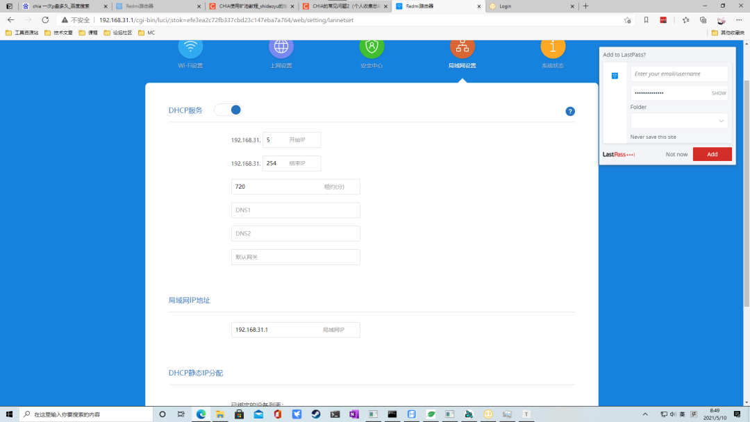
Change the default gateway field to the IP of the bypass router, 192.168.31.2. Finally, restart the router, and the network configuration is complete. Now our home network transformation is finished, and we are no longer afraid of high loads! This lays the foundation for the multimedia entertainment center we will build later.

Click “Read the original text” to get more valuable articles!