This experiment uses Arduino to directly drive the 1602 LCD to display text. The 1602 LCD is widely used in applications. The original 1602 LCD used the HD44780 controller, and now various manufacturers’ 1602 modules basically use compatible ICs, so their characteristics are generally consistent.1602LCD main technical parameters:
Display capacity is 16×2 characters;
Chip operating voltage is 4.5~5.5V;
Operating current is 2.0mA (5.0V);
The module’s optimal operating voltage is 5.0V;
Character size is 2.95×4.35 (W×H) mm.1602 LCD pin definitions
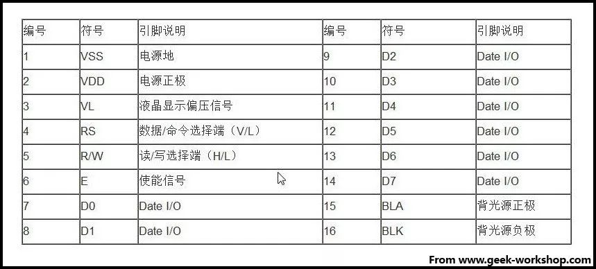
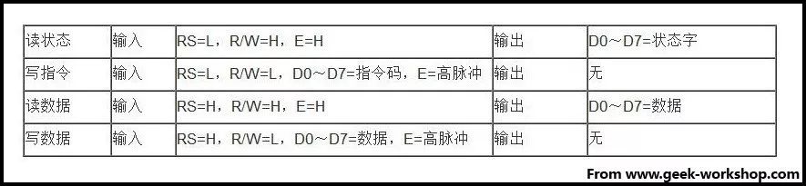
Interface description:1、Two power supplies: one for the module and one for the backlight, usually powered by 5V. In this experiment, the backlight can also work with 3.3V power.2、VL is the pin for adjusting contrast, using a potentiometer of no more than 5KΩ for adjustment. In this experiment, a 1KΩ resistor is used to set the contrast. The connection is divided into high potential and low potential, and in this experiment, the low potential connection method is used, with a 1KΩ resistor connected to GND.3、RS is a pin present on many LCDs, it is the command/data selection pin; when this pin is high, it indicates a data operation; when low, it indicates a command operation.4、RW is also a pin present on many LCDs, it is the read/write selection pin; when this pin is high, it indicates a read operation; when low, it indicates a write operation.5、E is also a pin found on many LCD modules, it usually sends a positive pulse to notify that data can be read after the signal on the bus stabilizes; when this pin is high, the bus is not allowed to change.6、D0—D7 are 8-bit bidirectional parallel buses used to transmit commands and data.7、BLA is the positive terminal of the backlight, BLK is the negative terminal of the backlight.The basic operations of the 1602 LCD are as follows:
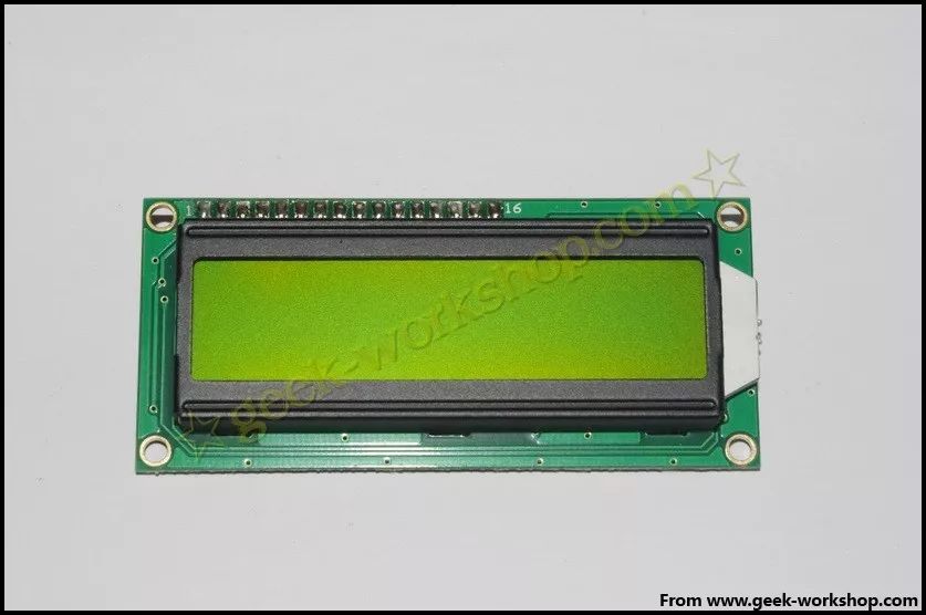
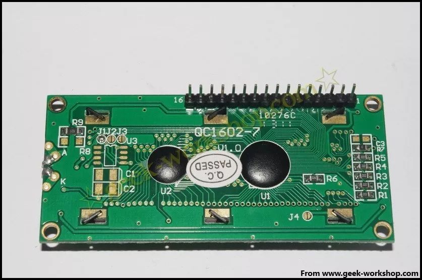
The following image shows the actual 1602 LCD.
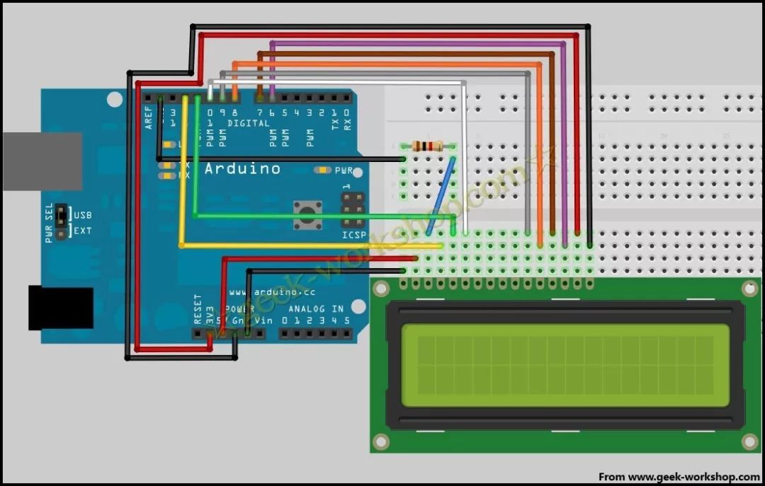
The 1602 communicates directly with the Arduino. According to the product manual, there are 8-bit connection method and 4-bit connection method. Under normal usage, the 8-bit method occupies almost all the digital ports of the Arduino. If you want to connect more sensors, there won’t be enough ports. In this case, how to handle it? We can use the 4-bit connection method.The hardware connection method for the 4-bit method is shown in the following image. Note that we only need to write, so we can directly connect RW to ground.
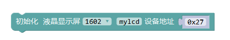
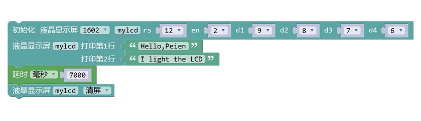
The program block code for MiSiQi is as follows. Note that this initialization block for the LCD can only be seen in the advanced view of MiSiQi.
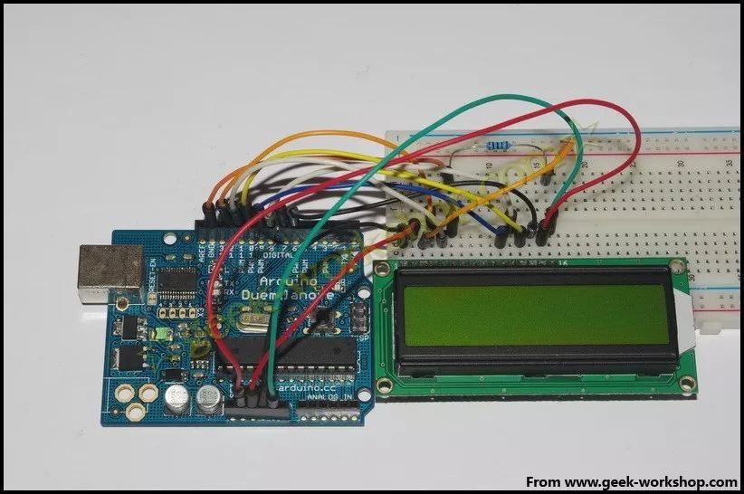
After connecting the hardware, upload the code above to the control board and check the effect. If you find display issues, it may be that the pin declarations from d1 to d4 are reversed; change them to 6789. The photo below shows the final actual wiring diagram. Make sure to confirm the positions of the rs, en, and rw pins.
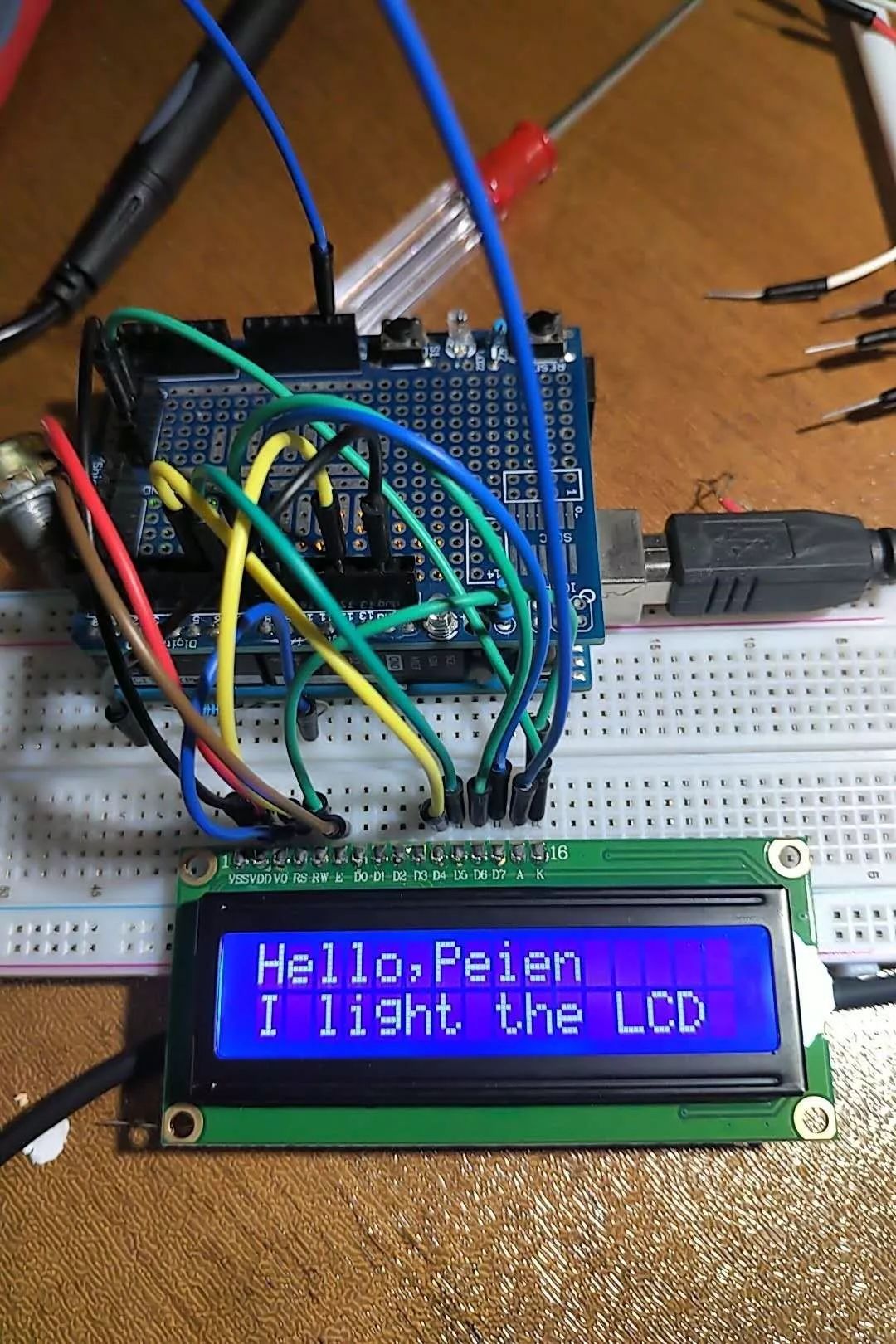
I have already purchased this component, so I can only use the four-wire connection method. It is highly recommended to buy an LCD with I2C read/write capability, which can reduce the number of connections and can use the initialization program block in the normal view of MiSiQi.