Light Up an LED
Overview
The purpose of this tutorial is to light up an LED using a program, which will automatically turn off after 3 seconds. In all programming languages, the first program is called hello world, and today’s LED lighting tutorial is essentially the hello world of hardware programming, making it a very simple example.
Through this lesson, we will learn:
-
Initial experience with hardware programming
-
Using a breadboard
-
Principles of LED
-
Controlling hardware via
GPIO
Required Hardware
-
Raspberry Pi x1
-
Breadboard x1
-
Dupont wires x2
-
LED light x1
Explanation of Terms
Below is a brief introduction to some electronic components and technical terms involved in this experiment:
Breadboard
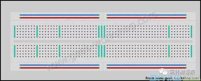
A breadboard is designed for solderless experiments with electronic circuits. The board has many small sockets, allowing various electronic components to be inserted or removed as needed, eliminating the need for soldering, saving assembly time, and allowing components to be reused, making it ideal for assembling, debugging, and training in electronic circuits.
Typically, the top and bottom rows are connected to the power and ground lines, while connections between components are made through the columns in between. Every five columns of grids form a group, and there is a groove in the middle to separate the left and right sections.
LED Light
LED stands for Light Emitting Diode. It has two legs, the longer leg is positive, and the shorter leg is negative. When current flows through, the LED lights up.
GPIO
GPIO (General Purpose I/O Ports) refers to general input/output ports, which are essentially pins that can output high or low signals or read the state of the pins—whether high or low. GPIO is an important concept, allowing users to interact with hardware (like UART), control hardware (like LEDs and buzzers), and read the working status signals of hardware (like interrupt signals). The use of GPIO is widespread, and mastering GPIO is almost equivalent to mastering hardware operation capabilities.
Now, let’s take a look at how GPIO on the Raspberry Pi works. Here is the front view of the Raspberry Pi:
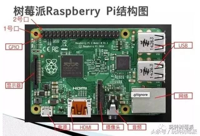
There are 40 pins, which serve as interfaces for the Raspberry Pi to control external sensors, known as GPIO. How are these 40 pins numbered? If we number them according to their physical position, there’s a simple rule to remember: the pin closest to the corner is pin 2. The adjacent one is pin 1; please refer to the diagram above for specifics.
So, what are the specific uses and definitions of these 40 pins? Please see the diagram below:
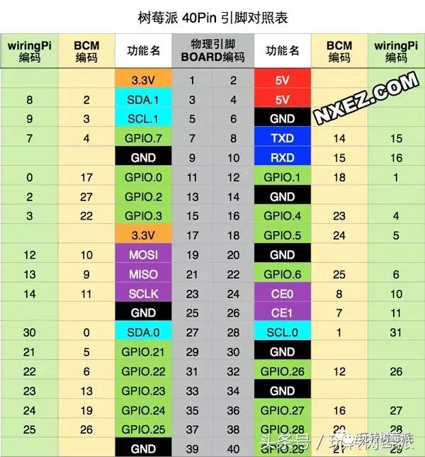
(This diagram will be used frequently, so it is recommended to save it for future reference)
This diagram provides a comprehensive definition, mainly because there are different numbering rules for these 40 pins. Although the names of the different rules vary, their actual uses are consistent. Here, we will only learn one numbering rule, which is the physical position numbering, making physical connections easier.
For example, pin 1 outputs a voltage of 3.3 volts; if you measure the voltage of this pin with a digital multimeter, it will consistently show 3.3 volts.
For example, pin 2 outputs a voltage of 5 volts; if you measure the voltage of this pin with a digital multimeter, it will consistently show 5 volts.
For example, pin 6 is a GND, which means ground; if you measure the voltage, it will show 0 volts.
For example, pin 11 is marked with a green icon, next to which is written GPIO17. This interface is a general-purpose interface that can be used for input or output. If set to output, it can output high or low voltage. A high voltage output is 3.3 volts, and a low voltage output is 0 volts. This can be controlled via a program. GPIO17 is merely another numbering method, which we can ignore here.
If a constant voltage is needed for a circuit, you can choose the corresponding interface for 3.3v or 5v.
If a varying voltage is needed for a circuit, you can choose the green GPIO interfaces, such as 11, 12, 13, 15, etc.
Python GPIO
The more precise name for this library is raspberry-gpio-python, which is recommended in the official Raspberry Pi documentation and is easy to get started with. The Python GPIO is a small Python library that helps users perform Raspberry Pi-related I/O operations. However, the Python GPIO library does not yet support SPI, I2C, or 1-wire bus interfaces. Besides Python GPIO, there are many Python extension libraries (like webiopi), and it’s undeniable that Python is very suitable for Raspberry Pi, which in turn is also very suitable for Python.
RPIO
This is a JavaScript library for operating GPIO, with method names and parameters very similar to Python GPIO. For more information, please visit the official website.
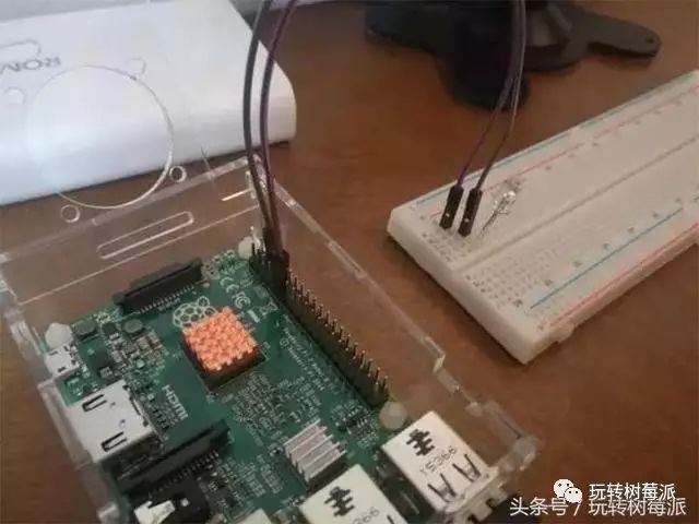
Wiring Diagram
Before connecting the hardware circuit, the first thing to do is to shut down the Raspberry Pi and disconnect the power. Because if the Raspberry Pi motherboard is powered on while connecting the circuit, it may lead to damage to electronic components, so it is essential to remember:
The motherboard must be powered off when connecting the circuit.
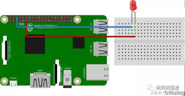
The image is drawn using Fritzing; for more example images, please visit the Fritzing official website.
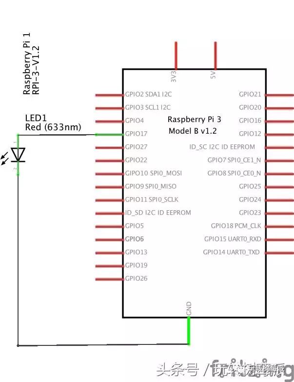
Circuit Schematic
Example Code
After wiring, the next step is to write the code. To control GPIO with Python, the easiest way is to use some Python libraries, like the built-in
RPi.GPIO
of the Raspberry Pi system.
This article details how to use
RPi.GPIO
to control GPIO, of course, you can use any language you prefer to control GPIO.
Importing the RPi.GPIO Module
You can import the
RPi.GPIO
module using the following code.
import RPi.GPIO as GPIOOnce imported, you can use the functions of the GPIO module. If you want to check whether the module was imported successfully, you can write it like this:
try: import RPi.GPIO as GPIOexcept RuntimeError: print("Import error")Pin Numbering
In RPi.GPIO, both GPIO pin numbering methods on the Raspberry Pi are supported.
The first numbering is
BOARD numbering
, which corresponds to the physical pin numbering on the Raspberry Pi circuit board. The benefit of using this numbering is that your hardware will always work, without worrying about Raspberry Pi version issues. Thus, after upgrading the circuit board, you do not need to rewrite connectors or code.
The second numbering is
BCM rule
, which is a lower-level working method that corresponds to the channel numbering in Broadcom’s system-on-chip. When using a pin, you need to look up the correspondence between the channel number and the physical pin number. For different versions of Raspberry Pi, the scripts you write may not be universally applicable.
You can specify a numbering rule (mandatory) using the following code:
GPIO.setmode(GPIO.BOARD) # orGPIO.setmode(GPIO.BCM)The following code will return the set numbering rule:
mode = GPIO.getmode()Warning
If
RPi.GPIO
detection finds that a pin has been set to a non-default value, you will see a warning message. You can disable the warning with the following code:
GPIO.setwarnings(False)Pin Setup
Before using a pin, you need to set it as input or output. The code to configure a pin is as follows:
# Set the pin to input modeGPIO.setup(channel, GPIO.IN)# Set the pin to output modeGPIO.setup(channel, GPIO.OUT)# Set the default value for the output pinGPIO.setup(channel, GPIO.OUT, initial=GPIO.HIGH)Release
Generally, when the program reaches the end, it is necessary to release resources. This good habit can avoid accidental damage to the Raspberry Pi. Release the pins used in the script:
GPIO.cleanup()Note that GPIO.cleanup() will only release the GPIO pins used in the script and will clear the set pin numbering rules.
Output
To light up an LED or drive a device, you need to provide them with current and voltage, and this step is also straightforward; you just need to set the output state of the pin. The code is as follows:
GPIO.output(channel, state)The state can be set to 0 / GPIO.LOW / False / 1 / GPIO.HIGH / True. If the numbering rule is GPIO.BOARD, then the channel corresponds to the pin number.
If you want to set multiple pins at once, you can use the following code:
chan_list = [11,12]GPIO.output(chan_list, GPIO.LOW)GPIO.output(chan_list, (GPIO.HIGH, GPIO.LOW))You can also use the Input() function to read the state of an output pin and use it as an output value, for example:
GPIO.output(12, not GPIO.input(12))Reading
We often need to read the input state of a pin. To get the input state of a pin, use the following code:
GPIO.input(channel)Low level returns
0 / GPIO.LOW / False
, high level returns
1 / GPIO.HIGH / True
.
If the input pin is in a floating state, the value of the pin will be fluctuating. In other words, the value read is unknown because it is not connected to any signal until a button or switch is pressed. Due to interference, the input value may change repeatedly. The following code can solve this problem:
GPIO.setup(channel, GPIO.IN, pull_up_down=GPIO.PUD_UP) # orGPIO.setup(channel, GPIO.IN, pull_up_down=GPIO.PUD_DOWN)It should be noted that the reading code above only retrieves the current instantaneous input signal of the pin.
If real-time monitoring of pin status changes is needed, there are two methods. The simplest and most primitive way is to check the input signal value at intervals, which is called polling. If your program reads at the wrong time, it is likely to miss the input signal. Polling is executed in a loop, which can be resource-intensive. Another way to respond to GPIO input is to use interrupts (edge detection), where the edge refers to the change of the signal from high to low (falling edge) or from low to high (rising edge).
Polling Method
while GPIO.input(channel) == GPIO.LOW:Edge Detection
The edge refers to the change in signal state, either from low to high (rising edge) or from high to low (falling edge). Generally, we care more about the edge of the input state rather than the value of the input signal. This edge of the state is called an event. First, let’s introduce two functions:
-
The wait_for_edge() function is used to block the program from continuing until an edge is detected. In other words, the earlier example of waiting for a button press can be rewritten as:
channel = GPIO.wait_for_edge(channel, GPIO.RISING, timeout=5000)if channel is None: print('Timeout occurred')else: print('Edge detected on channel', channel)-
The add_event_detect() function listens to a pin; once the input state of the pin changes, calling the event_detected() function will return true, as shown in the following code:
GPIO.add_event_detect(channel, GPIO.RISING) # add rising edge detection on a channeldo_something()# The following code should be placed in a thread loop.if GPIO.event_detected(channel): print('Button pressed')The code above requires you to create a new thread to loop and check the value of event_detected(), which is somewhat cumbersome.
However, another way to easily detect the state is to directly pass a callback function:
def my_callback(channel): print('This is an edge event callback function!') print('Edge detected on channel %s'%channel) print('This runs in a different thread than your main program')GPIO.add_event_detect(channel, GPIO.RISING, callback=my_callback)If you want to set multiple callback functions, you can do it like this:
def my_callback_one(channel): print('Callback one')def my_callback_two(channel): print('Callback two')GPIO.add_event_detect(channel, GPIO.RISING)GPIO.add_event_callback(channel, my_callback_one)GPIO.add_event_callback(channel, my_callback_two)Note: When a callback is triggered, the callback functions do not execute simultaneously but are called in the order they were set.
Alright, after explaining a lot about the function library usage, it’s time for a simple experiment:
#!/usr/bin/env python
# encoding: utf-8
# Import the RPI.GPIO module and alias it as GPIO
import RPi.GPIO as GPIO
# Import the time module
import time
# Declare GPIO to use physical numbering, which means pin 11 is physical pin number 11GPIO.setmode(GPIO.BOARD)
# Declare pin 11 to be used in output modeGPIO.setup(11, GPIO.OUT)
# Set pin 11 to high voltage, which means pin 11 becomes 3.3 volts
# After executing this line of code, pin 11 will become high voltage,
# then according to the circuit principle, the LED light will light upGPIO.output(11, GPIO.HIGH)
# Program sleeps for 3 seconds, during which the LED light will remain lit
time.sleep(3)
# Set pin 11 to low voltage, which means pin 11 becomes 0 volts, the same as GND
# After executing this line of code, pin 11 will become low voltage, thus the LED light will turn offGPIO.output(11, GPIO.LOW)
# Restore the state of all GPIO pins to initialization; it is a good habit to execute this at the end of the code
GPIO.cleanup()
Save the file as
led.py, and run it to see if the LED light turns on for 3 seconds and then turns off.
sudo python led.pyFinal Effect