This article is suitable for students who have studied LCD displays but do not fully understand them. The author uses the battleship STM32.
In this article, the author will discuss three topics: FSMC-related configuration, principles of displaying a string of characters, and principles of displaying Chinese characters. Let’s get to the point →_→
1. FSMC-related configuration (the author uses FSMC_A10):
First, let’s take a look at a good article about FSMC, from someone else’s blog (but it seems the website doesn’t allow links, so go find resources online yourself →_→
We won’t discuss the introduction of FSMC here; there’s plenty online →_→. Instead, let’s discuss why the FSMC address line is connected to the RS pin of the TFTLCD, and how we write data/commands to the LCD.
FSMC is known as the Flexible Static Memory Controller. It is termed ‘flexible’ because by setting special function registers, FSMC can issue corresponding data/address/control signal types based on different external memory types to match the signal speed (this point is very important and will be mentioned later).
Let’s briefly explain why we don’t connect the STM32’s IO pins directly to the corresponding pins of the LCD (you can see the link I posted above for clarity). Essentially, it is cumbersome to operate and inefficient. FSMC treats the TFTLCD as an SRAM device, and its operation timing is completely similar to that of SRAM, the only difference being that the TFTLCD has an RS signal but no address signal.
The TFTLCD uses the RS signal to determine whether the transmitted data is a command or data, which can essentially be understood as an address signal. For example, if we connect RS to A10 (of course A0-Axx can also work). So how does the LCD determine whether we are writing a command or data? Here’s the key point!!
Using the battleship’s program as an example:
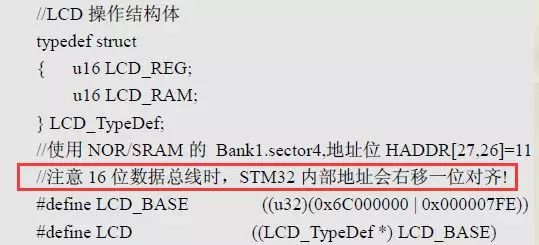
Here, because the data line width is 16 bits, HADDR[25:1] -> FSMC[24:0], which is equivalent to a right shift by one bit. Below is the offset given by the battleship for A10:

0x6c000000 should not be a problem for everyone. Logically, the offset for A10 should be 2 to the power of 11 (0-10) = 2048, which in hexadecimal is 800, and that is two digits larger than 7FE!
(Here’s a quick review of basic knowledge: RS=0 means write command; RS=1 means write data.)
Why is that? Here’s how I understand it (by reverse deduction): According to my thinking, if we take the address of LCD->LCD_REG as 0x6c000800, when the address is shifted right, the 10th bit is no longer 0, but 1. Corresponding to RS=1, this means it is no longer writing a command but writing data; and because of the structure member alignment rules, the address of LCD->LCD_RAM is 0x6c00802, and when the address is shifted right, the 10th bit is also 1, corresponding to RS=1. It is still writing data!!!!
At this point, everyone should understand. If we calculate normally, RS would only equal 1, and we wouldn’t distinguish between writing a command and writing data.
Therefore, we need to subtract two from the offset of A10. This gives us the battleship’s 0x000007FE. The address of LCD->LCD_REG becomes 0x6c0007FE. When the address is right shifted by one bit, the 10th bit is 0, corresponding to RS=0, which means writing a command to the LCD; and because of the structure member alignment rules, the address of LCD->LCD_RAM becomes 0x6c000800. When the address is right shifted by one bit, the 10th bit is 1, corresponding to RS=1, which means writing data to the LCD. This way, FSMC can distinguish whether the transmitted data is a command or data. →_→ Mission accomplished!
At this point, someone might ask: How can we complete reading and writing with just the control of the A10 line? Who controls the levels of those dozens of pins?
The mysterious ‘figure’ is the FSMC we mentioned earlier! First, let’s look at a write register function on the battleship:
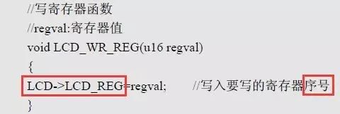
In the first image: here, LCD->LCD_REG is an address (0x6c000007FE), and the register number refers to the register address defined in the LCD manual. As long as we write a variable (address) to the address of LCD->LDC_REG, since this address is under the jurisdiction of FSMC, FSMC will bravely step in to manage this. FSMC will automatically generate the corresponding timing, including CS, WR, RD, and IO direction, all controlled by FSMC! This greatly facilitates our control of the LCD.
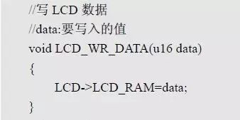
In the second image: here, LCD->LCD_RAM is also an address (0x6c00000800), and LCD->LCD_RAM=data; writes data to this register address.
2. The principle of displaying a string of characters (this section will just provide a process overview, the author uses the battleship):
1. For example, if we want to display a string LCD_ShowString(x,x,x,”hello 21ic”); x: refers to some coordinates and font size parameters, let’s not worry about that →_→
2. Then we need to call the character display function: LCD_ShowChar(); to retrieve the entire dot matrix of a character.
3. Characters are composed of dots, so in the character function, we keep calling the point-drawing function LCD_DrawPoint(); to draw dots (writing color values to LCD->LCD_RAM, where this color value is defined as a 16-bit address in lcd.h).
4. Thus, after the initialization of the LCD screen in lcd_init() (setting display parameters), it can be displayed.
5. Let’s briefly analyze the principles of overlay and non-overlay →_→
Overlay means that if the dot matrix of a character is ‘1’, we use the assigned brush color; if it is ‘0’, we assign the background color (the background color of the character is unrelated to the full-screen background color). There’s no problem here! Because when displaying in the end, there’s an overlay effect. First, the full-screen color is displayed, and then on top of that, your character is overlaid. This is how overlay and non-overlay (only one brush color) are displayed. Due to the author’s unclear explanation, it might not be very understandable, so think it over yourself →_→
3. The principle of displaying Chinese characters
Actually, the principle of displaying Chinese characters is the same as that of displaying English characters. It’s very simple! The display principle is based on the byte size of your Chinese character’s font to draw dots.
Let’s briefly discuss: everyone knows that the display principle of letters involves two for loops (the author knows this), the first for controls the ‘rows’, and the second for controls the ‘columns’. Here are two examples: for displaying a 16*08 letter, the first for loops 16 times, and the second for loops 8 times; for displaying a 24*24 Chinese character, the first for loops 72 times, and the second for loops 8 times. Not sure if everyone has noticed a pattern here →_→
Pattern: The first for is the byte size occupied by the font, and the second for draws 8 bits each time (drawing 8 dots from the highest position of the column downwards). In the character display function, there’s a notation y-y0, which determines whether the number of dots in a column reaches 16 or 24. If so, x+1, moving to the next column.
In summary, the byte size of the Chinese character font is larger than that of the letter font. The modifications are mainly in the first for loop and the parameters in y-y0.