Three-phase asynchronous motors are widely used. When electricians are repairing motors, they often encounter some old motors that lack nameplates or markings, or the nameplates and markings are unclear. How to use a multimeter to determine and test the motor windings, number of poles, speed, etc., is discussed below.
1. Determining the Start and End Terminals of the Motor Windings
Determining the start and end terminals of the motor windings is a common issue encountered during maintenance.
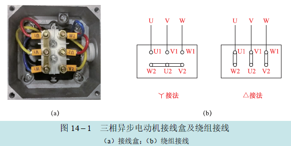
A three-phase motor has three windings that are spaced 120° apart, embedded in the stator core. Each row of windings has two output terminals, one for the start and one for the end. The start and end terminals of the motor windings, also known as the head and tail of the windings, are typically brought out from the motor’s junction box and are clearly marked. Generally, U1, V1, W1 are marked as the start terminals, and U2, V2, W2 as the end terminals, as shown in the diagram below.
There are two wiring methods for three-phase motors: one is star connection (Y), and the other is delta connection (Δ), as shown in the diagram below. When in use, whether the motor windings are connected in star or delta is not subjectively determined by the user, but must be correctly connected according to the markings on the nameplate. If the nameplate indicates “220/380V, Δ/Y connection,” it means that when the supply line voltage is 220V, the windings are connected in delta; when the supply line voltage is 380V, the windings are connected in star.
In recent years, domestically produced three-phase motors with a power greater than 4kW generally indicate on the nameplate “380V Δ connection,” which means that when using a 380V three-phase power supply, the stator windings are connected in delta. Regardless of whether it is a star or delta connection, correctly determining the start and end terminals of the windings is essential. When the six lead wires in the junction box of some old motors are neither connected nor marked, if one is not familiar with the connection rules, it is easy to misconnect the start and end terminals of the stator windings. Once put into use, this will create an incomplete rotating magnetic field, making startup difficult, producing vibration noise, causing unbalanced three-phase current, and easily burning out the stator windings.
01
Using Residual Magnetism Method to Determine the Start and End Terminals of the Motor Windings
This method utilizes the residual magnetism that exists on the rotor of a motor that has been previously operated under alternating current. When the rotor is manually rotated, the residual magnetism on the rotor will cut through the stator windings, inducing an electromotive force in the stator windings. At this point, the motor acts like a generator, and if the windings form a closed loop, induced current will be generated.
Since the induced electromotive force polarities of the start (or end) of the three-phase windings differ by 120°, if the three start (or end) terminals of the three-phase windings are shorted together, the sum of the three-phase induced currents will be zero. Therefore, the multimeter’s milliampere scale pointer will not move (current is zero) when connected between the two shorted points of the start and end. If it is not the three start (or end) terminals that are shorted, but rather the “start and end” that are shorted, the sum of the three-phase induced currents will not be zero, so the multimeter’s milliampere scale pointer will swing (current is not zero).
Before determining, set the multimeter to the R × 100Ω scale and measure the six lead wires in the motor’s junction box in pairs to find the three-phase windings, assigning hypothetical numbers to each phase as U1 – U2, V1 – V2, W1 – W2. Then proceed to connect as shown in the diagram below and set the multimeter to the DC current 5mA scale.
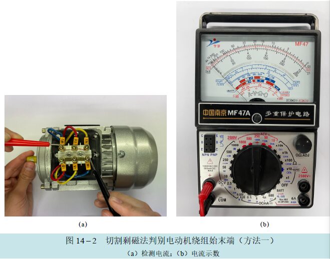
At this point, manually rotate the motor rotor. If the multimeter pointer does not move, it indicates that the connection of the start and end terminals of the windings is correct. If the multimeter pointer swings, it indicates that there is an error in the connection of the start and end terminals, and the connection should be adjusted and retested until the pointer remains still.
(2) Detection Precautions.
1) When using the residual magnetism method to determine the start and end terminals of the motor windings, the rotor of the motor must have residual magnetism, meaning the motor must have been previously operated or just powered.
2) Due to the asymmetry of the three-phase windings, even when connected correctly, the multimeter pointer may still show a slight deflection, but the deflection will be much smaller than when connected incorrectly.
02
Voltage Method to Determine the Start and End Terminals of the Motor Windings
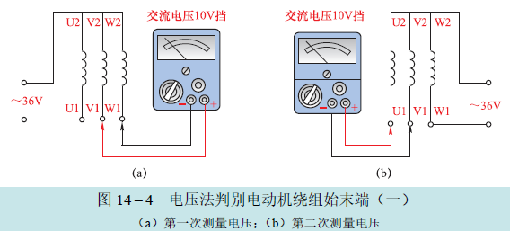
Before determining, first use the resistance scale of the multimeter to find the two ends of the three-phase windings and assign hypothetical numbers to each phase as U1-U2, V1-V2, W1-W2. Then connect the three-phase windings in a star configuration. Apply 36V AC power to one phase, and connect the multimeter between the other two phases, setting the range switch to the AC voltage 10V scale. The detection method is shown in the diagram below.
Measure once as shown in diagram (a) and once as shown in diagram (b). If the multimeter pointer does not move in both cases, it indicates that the connections shown in the diagrams are correct. If the pointers deflect in both cases, it indicates that the start and end terminals of the group that was not connected to the power supply are reversed. If only one pointer deflects while the other does not, it indicates that the start and end terminals of the phase that did not deflect are reversed.
2. Number of Poles and Speed of the Motor
The number of poles in a three-phase asynchronous motor refers to the number of magnetic poles in the stator magnetic field. The poles always appear in pairs, so the motor can have 2, 4, 6, 8, etc. The number of poles in the motor is determined by the speed required by the load, and the number of poles directly affects the speed of the motor. The more poles, the lower the speed; the fewer poles, the higher the speed. Two poles correspond to a high-speed motor with a speed of 2800-3000 r/min; four poles correspond to a medium-speed motor with a speed of 1400-1500 r/min; six poles correspond to a low-speed motor with a speed of 900-1000 r/min; eight or more poles correspond to an ultra-low-speed motor with a speed of less than 760 r/min.
01
Using Residual Magnetism Method to Determine the Number of Poles in Asynchronous Motors
(1) Determining the Number of Poles in Asynchronous Motors.
When the nameplate of the motor is unclear or missing, to find out the number of poles in the motor, the DC current scale of the multimeter can be used for testing and judgment, as shown in the diagram below.
Open the motor’s junction box, remove the original power lines and the star or delta connections, and use the multimeter’s R × 100Ω scale to find any two lead wires of one phase winding from the six motor lead wires.
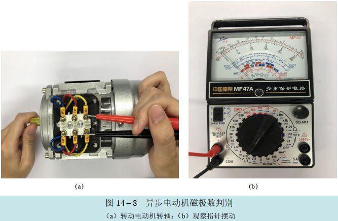
Then set the multimeter range switch to the DC small current 0.05mA or 0.5mA scale, and after replacing the probes with alligator clips, securely clamp them to the two lead wires of the identified winding. Manually rotate the motor’s pulley or shaft slowly and uniformly for one complete revolution, carefully observing the number of times the multimeter pointer swings.
Each swing of the multimeter pointer indicates a change in current polarity within that phase winding, allowing determination of the number of magnetic poles in the motor. If the pointer swings left and right once, the motor is a 2-pole motor; if it swings twice, it is a 4-pole motor. In other words, the number of swings of the pointer corresponds to the number of pole pairs in the motor.
(2) Detection Precautions.
1) The principle utilized in this method is that when the rotor of the asynchronous motor rotates uniformly for one revolution, the residual magnetic flux of the rotor cuts through the stator windings, inducing a small electromotive force that generates current, causing the multimeter pointer to swing.
2) If the motor has not been used for a long time, the multimeter pointer may not respond during testing. This is due to the loss of residual magnetism in the motor. In this case, simply connect the motor to the power supply using the proper method, run the motor for a few minutes, and after disconnecting the power, the stator windings will regain residual magnetism, allowing the number of poles to be determined using the above method.
02
Testing the Speed of Small Electric Motors
(1) Method for Testing the Speed of Small Electric Motors.
Small electric motors refer to three-phase AC motors with a diameter of less than 160mm or a rated power of less than 750W. Electricians often need to know the speed of these motors during use and maintenance, but they frequently encounter unclear nameplates and have no tachometers at hand. In such cases, a multimeter can be used to estimate the motor’s speed.
First, set the multimeter range switch to the resistance scale and find one winding from the motor’s lead terminals. Then set the multimeter range switch to the DC current 50μA scale, and it is best to replace the probes with alligator clips, securely clamping them to both ends of this winding. The detection method is shown in the diagram below.
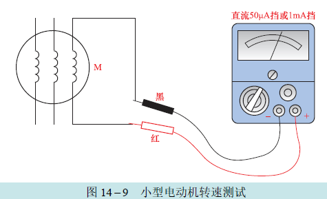
Then slowly rotate the motor shaft to make it rotate uniformly for one revolution. At this time, the multimeter pointer will swing left and right, and the number of swings will correspond to the number of magnetic pole pairs p of the motor. For example, if the rotor rotates once, the multimeter pointer swings left and right once (moving to the right and returning to the left counts as one swing), then p=1, which indicates a 2-pole motor.
In a 50Hz power supply system, the synchronous speed n of the motor is determined by the following formula:
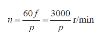
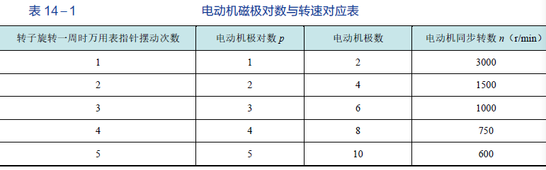
Clearly, the synchronous speed is inversely proportional to the number of pole pairs; the more pole pairs, the lower the speed. According to the table below, the speed of the motor can be roughly determined.
For three-phase asynchronous motors, the rotor speed n1 must be slightly lower than the synchronous speed n to operate normally. Generally, n1=(0.94~0.985)n.
(2) Detection Precautions.
The above method for estimating the speed of a three-phase motor can only be directly applied to motors with residual magnetism. If the motor does not have residual magnetism, it can be powered on and run for a period before using this method to measure its speed.
This article is adapted from “Mastering Multimeter Testing of Electronic Components from Beginner to Advanced.”