Linux | Red Hat Certified | IT Technology | Operations Engineer
👇 Join the technical exchange QQ group of 1000 people, note 【public account】 for faster approval

1. Physical Structure of the Disk
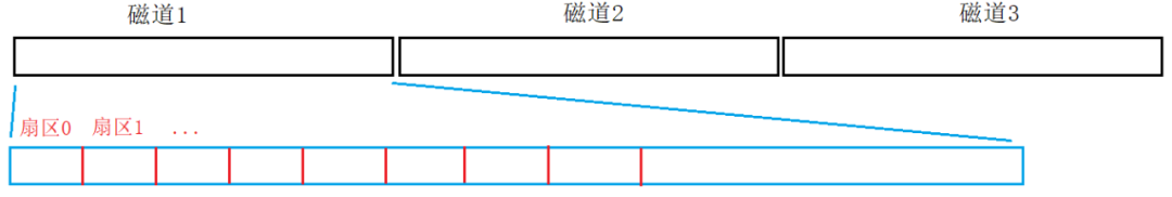
The physical structure of the disk is shown in the figure:

The specific physical storage structure is as follows:

The basic unit stored in the disk is a sector, and the size of a sector is generally 512 bytes or 4KB; here we assume it is 512 bytes. In a typical disk, a sector is 512 bytes, and all sectors of the same radius form a track.
Therefore, when we need to read data from a specific file, we first determine which disk surface it is on, then which track, and finally locate the sector based on the sector number. The method of locating sectors through the magnetic head, cylinder (track), and sector is called the CHS addressing method.
A regular file consists of attributes + content, which are essentially data occupying one or more sectors. Since we can use CHS to locate any sector, we can locate any number of sectors, thus reading or writing files from a hardware perspective.
2. Logical Abstraction of the Disk
We already know that if the OS can know the CHS address, it can access any sector. However, since the OS is software and the disk is hardware, to prevent hardware iteration changes, the OS must also change accordingly, and it must decouple the OS from the hardware, so the OS does not use the CHS address internally.
To reduce the frequency of IO operations, the basic unit size for IO operations between the OS and peripherals is 4KB (adjustable). Even if only one byte of data needs to be modified, the entire 4KB of data where this data resides must be loaded into memory, modified, and then written back to the disk, which is why we refer to the disk as a block device. The OS needs a new address for block-level access.
Consider the disk tracks as a continuous spatial structure:
Sectors are equivalent to continuous arrays; at this point, locating a sector only requires an array index. Since the OS performs IO in 4KB units, an OS-level file block must include 8 sectors.The OS does not care about the concept of sectors; the conventional access address for computers is done through the starting address + offset method, so when the OS accesses data blocks, it only needs to know the starting address of the data block + 4KB, treating the data block as a type.
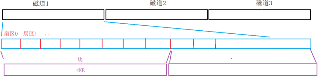
Thus, the address of a block is essentially an index N of an array, allowing us to use index N to locate any block in the future.This addressing method is called LBA, or Logical Block Addressing.
After obtaining the LBA address, it can be converted into the CHS address of the disk through simple mathematical calculations. For example, if LBA = 6500, the size of one disk surface is 5000, and the size of one track is 1000. The corresponding address is the 2nd disk surface, the 6th track, and the 500th sector.
From now on, the management of the disk is abstracted into the management of a large array.
3. File System
Due to the large size of disks, to manage them more conveniently, the OS partitions the disk blocks. After partitioning, each disk area is grouped. The specific structure is as follows:
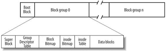
When the OS partitions the disk, it sets a Boot Block at the very beginning, which mainly stores OS-related content, such as the partition table, image address, etc. Generally, this partition exists in the 0th sector of the 0th track of the 0th disk surface. When the user boots up, the OS loads the disk driver, reads the partition table, then reads the OS’s address from the starting position of the specific partition, and loads the OS, at which point the OS is considered to be running.
After that, the OS forms many Block groups by grouping each partition. Each Block group has the 6 regions shown in the figure above.
1. Super Block
The Super Block stores all attribute information of the file system, including the type of file system, the overall situation of the group. The recorded information mainly includes: total number of blocks and inodes, number of unused blocks and inodes, size of a block and inode, time of last mount, time of last data write, time of last disk write, and other related file system information.
2. Group Descriptor Table
The GDT is the group descriptor, which saves detailed statistics and attribute information within the group. For example, what part of the content is from where to where, how much of this group has been used, etc.
3. inode Table
Generally, we refer to the collection of all attributes within a file as the inode node, typically sized at 128 bytes. A file will have one inode, and a group will have many files and many inode nodes, so there is a dedicated area within the group to protect these inode nodes, known as the inode Table.
Within the group, each inode table has its own inode number. The inode number itself is also an attribute of the corresponding file, and when Linux looks for a file, it also finds it through the inode number.
One inode corresponds to one file, and the inode attributes of that file have a mapping relationship with the data blocks corresponding to that file.
4. Data Blocks
The content of a file is variable and is saved using data blocks. Therefore, to save the content of a valid file, n data blocks are needed. If there are multiple files, multiple data blocks are required. The area where these data blocks reside is called Data Blocks. The default size of a data block is 4KB.
When Linux searches for a file, it first finds the inode of that file. In the inode structure, there is an int blocks[NUM] array that records the addresses of the data blocks storing the content of that file. In a group, more than 95% of the content is Data Blocks.
When the operating system needs to load a file, it only loads the inode node of that file. The inode node contains the mapping relationship of the data blocks of the file content, allowing the desired content to be loaded into memory based on the mapping relationship.
5. inode Bitmap
The inode Bitmap is a bitmap structure where each bit indicates whether an inode is free and available.
6. Block Bitmap
The Block Bitmap is a bitmap structure that records which data blocks in the Data Block have been occupied and which data blocks have not been occupied.
4. File Systems in Linux
In Linux, by using the ls command with the -i option, you can observe the inode of a file:
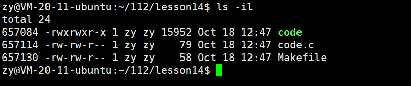
1. inode and File Name
The Linux system only recognizes inode values, and the inode attributes do not contain file names, as file names are only for user visibility.
Every file must exist in a directory, which is also a file and has its own inode value and corresponding data blocks. The database block of the directory stores the mapping relationship between the file names and inode values of that directory, and within the directory, the file names and inode numbers are mutually key values.
The inode number is uniquely valid within a partition and cannot be used across partitions. Based on the inode number, the group in which that file is located within the current partition can be determined.
2. File Operations: Create, Delete, Query, Modify
2.1. Viewing File Content
When a user accesses the content of a target file, it must be done in a specific directory, and the specific process is as follows:
First, find the inode number of the target file in the current directory.
A directory is also a file and belongs to a partition, and within that partition, find the group by the target file’s inode number, and locate the target file’s inode in the inode Table area of that group.
Through the mapping relationship of the target file’s inode and the corresponding Data blocks, find the data blocks of that file, load them into the OS, and finally display them on the monitor.
2.2. Deleting a File
When a user deletes a target file, the specific process is as follows:
In the current directory, find the target file’s inode number based on the file name.
Find the target file’s inode based on the inode number, and set the corresponding bit in the block bitmap to 0 based on the mapping relationship with the corresponding Data blocks.
Set the corresponding bit in the inode bitmap to 0 based on the inode number.
2.3. Creating a File
When a user creates a target file, it must be created in a directory. The specific process is as follows:
The OS scans the inode bitmap in the group where the directory is located, finds an empty position, and sets it to 1, obtaining the inode number.
Fill the default attributes of the created file into the corresponding inode.
Add a new mapping relationship between the file name and inode number in the Data blocks of the current directory.
2.4. Supplementing Content
The content above includes partitioning, grouping, filling system attributes, etc. All these tasks are done by the OS. After partitioning is complete, to ensure the partition can be used normally, it needs to be formatted, which means the OS writes the management attribute information of the file system to the partition and performs area partitioning. If the area partitioning has already been done, the formatting operation clears the bitmap structure and sets the attribute fields to their initial state.
The file system establishes a mapping relationship between inodes and Data blocks through arrays. Since Data blocks are large, to map them, arrays use direct indexing, secondary indexing, and tertiary indexing methods. Since this is not the main content, it will not be explained further.
In the file system, there may be cases where inodes are not fully used while Data blocks are exhausted, or inodes are exhausted while Data blocks still have some remaining. For example, if only one file is created and data is continuously added to that file, it consumes Data blocks. Alternatively, if many empty files are continuously created, it consumes inodes. Currently, there is no way to avoid this problem.
5. Soft and Hard Links
1. Soft Links
Command to create a soft link: ln -s [target file] [soft link file name]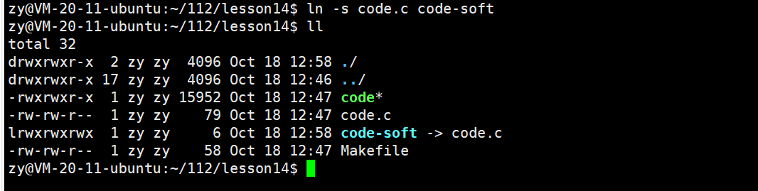
Using code-soft linked to code.code-soft is a link file.
It is observed that code-soft and code.c have different inode numbers, indicating that the soft link is an independent link file. It has its own inode number, which must have its own inode attributes and content. The content of the soft link is the path of the file it points to, allowing users to quickly find the target file.
The specific use of a soft link is: if the path of a target file is very deep, every time we access the target file, we have to write a long path, which is not efficient. In this case, we can use a soft link to create a link file in the working directory for convenient access to the target file, similar to a shortcut in the Windows system.
2. Hard Links
Command to create a hard link: ln [target file] [hard link file name]The specific operation is as follows:
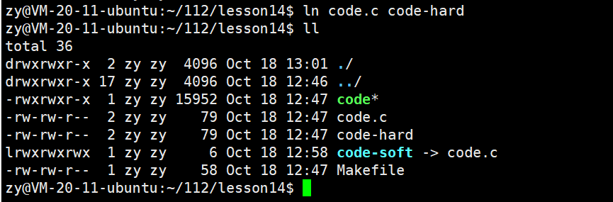
Using code-hard linked to code.c.code-hard is a regular file.
It is observed that code-hard and code.c have the same inode number, indicating that the hard link is the same file as the original file. The hard link only establishes a new mapping relationship between the new file name and the old inode number, modifying only the content of the current directory.
Both code-hard and code.c have their hard link count changed to 2. This means that there are now two ways to find that file, corresponding to two file names. The hard link count is essentially a reference count.
Now we use the unlink command to delete the hard link:
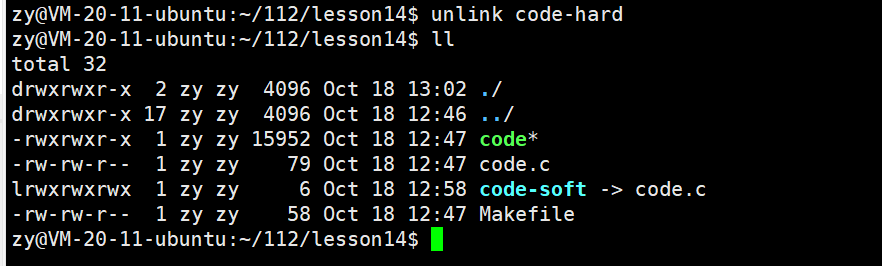
At this point, the hard link count of the file changes back to 1.
Next, we create a directory file and observe the hard link count:
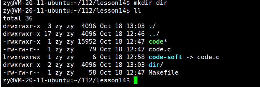
It can be seen that the default hard link count of the directory file is 2.This is because directory files inherently have two hard links, one being their own name and the other being the ” . ” symbol inside that directory.If the directory file contains other directory files, then the hard link count of that directory file will become 3: its own name, the ” . ” symbol inside that directory, and the ” .. ” symbol inside the directory.
Hard links are not allowed for directories in Linux.
3. Why Have Hard Links
(1) File Backup and Redundancy
Providing additional file access paths: After creating a hard link, multiple file names can point to the same inode (index node). This means that the same file content can be accessed through different path names. If one path name is accidentally deleted or corrupted, the file can still be accessed through other hard link paths, serving as a backup.
Increasing file reliability: In some critical application scenarios, creating hard links can ensure that files can be accessed from multiple locations, reducing the risk of data loss due to the loss or corruption of a single file name.
(2) File Management and Organization
Facilitating file sharing: Multiple users or programs can access the same file simultaneously through different hard link paths without needing to duplicate the file content, saving disk space and time. For example, in a team project, different members can access shared files through hard links in their respective working directories, enabling collaborative file operations.
Simplifying file structure: Hard links can be used to organize the file system, allowing related files to be accessed through multiple paths. This is very useful for complex file system structures or situations requiring flexible file access.
(3) Compatibility with Traditional File Systems
Compatibility with legacy systems and tools: Many traditional file system tools and applications can understand and handle hard links. This allows familiar file management methods to continue being used when migrating from old systems to Linux or working in different file system environments.
Stability and reliability: The implementation of hard links is based on the underlying structure of the file system, making it relatively stable and reliable. Unlike certain advanced file system features that may vary across different operating system versions or file system implementations, hard links generally provide consistent behavior.
6. Dynamic and Static Libraries
The essence of dynamic and static libraries is the “semi-finished product” of executable programs.
Generating an executable program from a piece of code requires the following four steps:
Preprocessing: Complete header file expansion, remove comments, macro replacement, conditional compilation, etc., ultimately forming xx.i file
Compilation: Complete syntax analysis, lexical analysis, semantic analysis, symbol aggregation, and after checking for errors, compile the code into assembly instructions, ultimately forming xx.s file
Assembly: Convert assembly instructions into binary files, xx.o file
Linking: Link the generated .o files to form the final executable program

For course inquiries, add: HCIE666CCIE
↑ Or scan the QR code above ↑
What technical points and content do you want to see?
You can leave a message below to tell Xiao Meng!