The GPIO pin numbering on the Raspberry Pi is divided into two types: Physical Pin numbering and BCM numbering (Broadcom SOC Channel). The Physical Pin numbering indicates the physical position of each GPIO pin on the expansion board, while the BCM numbering is used internally by the GPIO controller on the SOC chip.


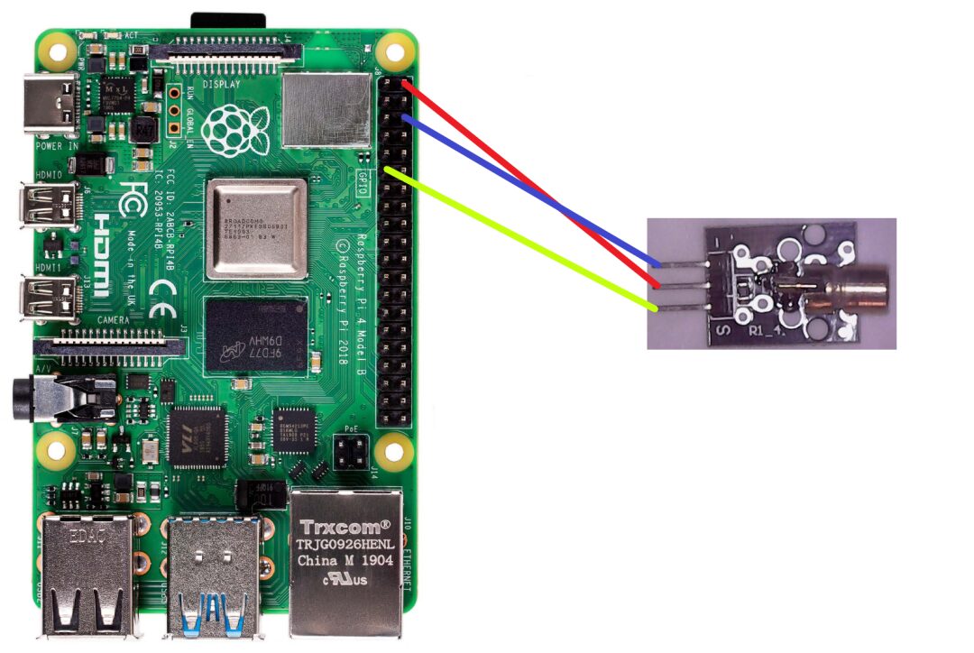
To connect the Raspberry Pi (GPIO), you will need some basic hardware:
-
Raspberry Pi Board: Ensure the Raspberry Pi is successfully booted and has a GPIO interface.
-
Electronic Components: This can be LEDs, buttons, sensors, and other electronic devices.
-
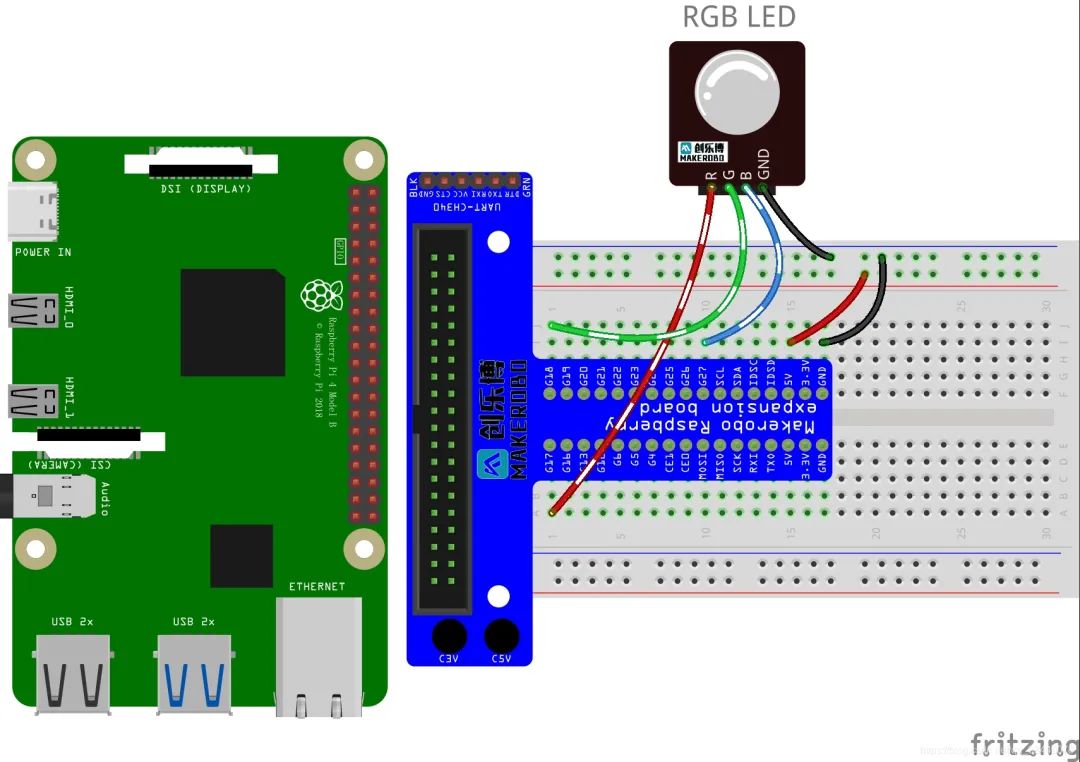
Connection Wires: Typically, a breadboard or DuPont wires are used to connect the Raspberry Pi and external electronic devices.
-
Power Supply: Ensure that external electronic devices have sufficient power supply to execute your commands accurately.
Before connecting the Raspberry Pi GPIO, you need to know the functions and numbers of each pin. You can find relevant information in the official documentation or online.
The steps to connect GPIO are as follows:
-
Determine the required GPIO pin. Choose an appropriate GPIO pin as an input or output port based on your needs.
-
Connect the electronic components. Properly insert the selected components into the breadboard or use direct wiring methods. Be careful to use the correct type of wiring and avoid cross connections that could cause damage.
-
Connect to the Raspberry Pi. Connect to the corresponding GPIO number on the Raspberry Pi using correctly connected wires. For digital input, it must connect to the linear pins on the Raspberry Pi, and in some cases, a fixed resistor must be used.
-
Testing and Programming. You can use programming languages like Python to test and control the connected computing devices. Before running any code, ensure you have set the correct GPIO pins in your program to avoid unnecessary damage and risks.
Note that during the connection and testing process, attention must be paid to current, voltage, and PN resistor circuit design factors to avoid burning out the Raspberry Pi or external electronic devices.
-
Import the Module. Import the RPI.GPIO library in your Python program: import RPi.GPIO as GPIO.
-
Set the GPIO Mode. Set GPIO to one of three different modes in your code: Input, Output, or Board. Typically, start by setting the mode to Board: GPIO.setmode(GPIO.BOARD).
-
Configure the GPIO Pins. Configure the GPIO pins you need to use and their respective direction (input or output): GPIO.setup(channel, GPIO.IN/OUT). The channel here can be the Physical Pin numbering or BCM board pin numbering.
-
Control the GPIO Pins. Use appropriate values to switch the GPIO pins to the desired state; if it is an output state, it would be High (high level) or Low (low level); if it is an input state, detect the current state: GPIO.output(channel, state) and GPIO.input(channel)
-
Clear Pin Settings. After completing all tasks, you must release the GPIO pins and clear previous settings so they can revert to their initial state: GPIO.cleanup()
import RPi.GPIO as GPIO
GPIO.setmode(GPIO.BOARD)
GPIO.setup(11, GPIO.OUT)
while True:
    GPIO.output(11, GPIO.HIGH)
    print("LED ON")
    sleep(1)
    GPIO.output(11, GPIO.LOW)
    print("LED OFF")
    sleep(1)
GPIO.cleanup()
import RPi.GPIO as GPIO
import time
GPIO.setmode(GPIO.BOARD)
GPIO.setup(11, GPIO.OUT)
try:
    while True:
        GPIO.output(11, True) # Set GPIO11 pin to high level
        time.sleep(1)         # Last for one second
        GPIO.output(11, False) # Set GPIO11 pin to low level
        time.sleep(1)         # Last for one second
except KeyboardInterrupt:
    GPIO.cleanup()          # Clear GPIO pins and exit application

Want to know more
Quickly scan the code to follow us