🚩 Have you encountered these pitfalls? You wrote the LED code, but it blinks inconsistently? You want the microcontroller to “blink the light + read the button” simultaneously, but it freezes? Don’t panic—you just need to understand the “timer” and “interrupt,” the two “little helpers” of the microcontroller!!
Today, using simple language and a step-by-step tutorial, I will help you easily grasp the concepts of “timer” and “interrupt”.
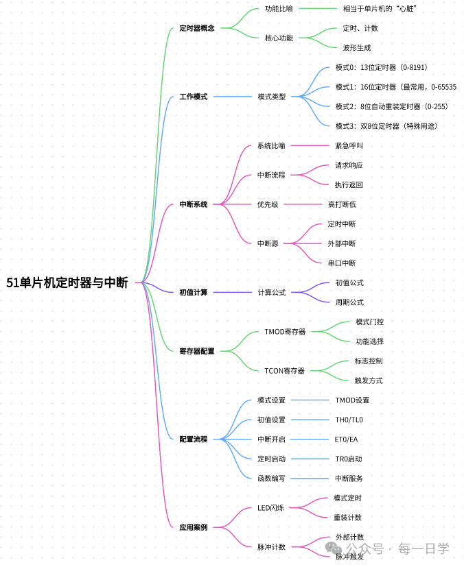
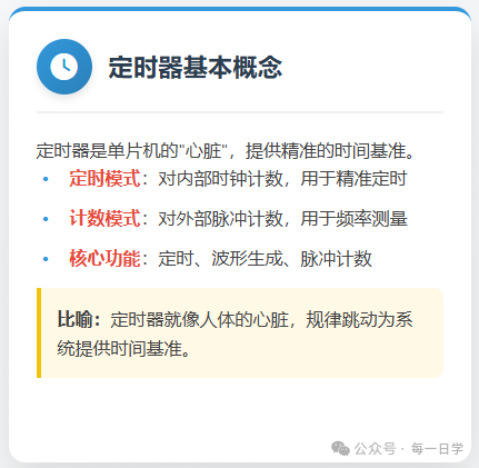
1. First, understand: Timer = the microcontroller’s “smart alarm clock” ⏰
Just as you rely on an alarm clock to wake up, the microcontroller also needs an “alarm clock”—this is the timer. It can accurately keep time and remind the microcontroller when “it’s time to do something,” without the CPU constantly monitoring the time.
(1) The timer can perform two core functions (just remember these two for beginners)
|
Function |
Similar to what in life? |
Common scenarios |
|
Timer mode |
Kitchen timer (rings when time is up) |
LED blinking, button debouncing, delays |
|
Counting mode |
Supermarket scanner (counts each scan) |
Counting button presses, measuring motor speed |
For example: If you want the LED to blink once every second, use the “timer mode”; if you want to know how many times a button has been pressed, use the “counting mode”—isn’t it straightforward?
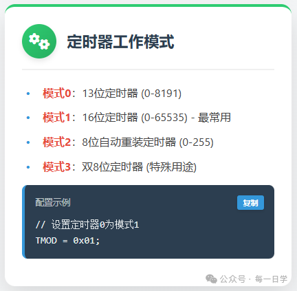
(2) Four working modes? Beginners only need to focus on “Mode 1”!
The timer has four modes, but 90% of beginner projects only use Mode 1 (16-bit timer), so there’s no need to remember the other modes for now, just focus on the essentials!
Here’s a “card” to help you distinguish (it’s clearer on mobile):
-
📌 Mode 0 (13-bit): Used in old projects, now rarely used
-
⭐ Mode 1 (16-bit): Counting range 0-65535, long enough timing (e.g., 1 second), a must-learn for beginners
-
📌 Mode 2 (8-bit auto-reload): Used only for serial communication, to be learned later
-
📌 Mode 3 (dual 8-bit): Used in special scenarios, rarely encountered
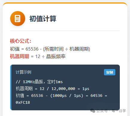
(3) Initial value calculation: No need for beginners to memorize formulas! Just follow along
The most dreaded “initial value” for beginners is actually just “how many minutes in advance should the alarm be set to ring.” Taking the most commonly used 12MHz crystal oscillator (usually included with the microcontroller) as an example, let’s calculate step by step:
Step 1: Calculate the “heartbeat interval of the microcontroller” (machine cycle)
The time it takes for the microcontroller to execute one minimum instruction is called the “machine cycle,” and the formula is very simple: Machine cycle = 12 ÷ crystal frequency Substituting 12MHz (12000000Hz): 12 ÷ 12000000 = 1 microsecond (μs) → This means: the microcontroller “ticks” once every 1 microsecond, 1000 microseconds = 1 millisecond (ms), 1000 milliseconds = 1 second (s).
Step 2: Calculate the initial value (the “advance time” for the alarm)
The timer starts counting from the “initial value” and counts up to 65535 before it “rings” (overflows), so the initial value formula is: Initial value = 65536 – (desired timing ÷ machine cycle)
For a practical example: Timing for 1 millisecond (1000 microseconds) Initial value = 65536 – (1000μs ÷ 1μs) = 64536 Convert 64536 to hexadecimal (no need to calculate it yourself, a mobile calculator can do it) → 0xFC18 → Just write in the code<span><span>TH0=0xFC; TL0=0x18;</span></span> and you’re good to go!
💡 Beginner’s benefit: Common initial value table (just copy)
|
Crystal frequency |
Timing |
Initial value (hexadecimal) |
|
12MHz |
1ms |
TH0=0xFC, TL0=0x18 |
|
12MHz |
50ms |
TH0=0x3C, TL0=0xB0 |
|
12MHz |
100ms |
TH0=0x00, TL0=0x60 |
2. Further understanding: Interrupt = the microcontroller’s “delivery phone” 📞
Having just a timer is not enough—if the microcontroller is currently “watching a show” (executing the main program), and the timer’s “alarm rings” (it’s time to blink the LED), how can it pause the show, handle the blinking, and then continue watching? This is where “interrupts” come in: like a delivery person calling, you pause the show → receive the delivery → return to continue watching, maximizing efficiency!

(1) Interrupts in 4 steps: as simple as receiving a delivery
Use a flowchart to help you understand (it’s also clear on mobile):
1. The delivery arrives (timer overflow/button pressed) → Send "interrupt request" 2. Pause the show (save the main program progress) → "Respond to interrupt" 3. Go to the door to receive the delivery (execute the interrupt service function, e.g., toggle LED) → "Process interrupt" 4. Return to the sofa to continue watching the show (return to the main program) → "Interrupt return"(2) Must-remember for beginners: 3 common "interrupt sources"These are the situations that will “ring the delivery phone”:
-
⏱️ Timer interrupt: The timer has reached the set time (e.g., 1ms)
-
🔘 External interrupt: Button pressed, sensor triggered (e.g., infrared sensing)
-
📡 Serial interrupt: The microcontroller receives messages from a computer/other devices
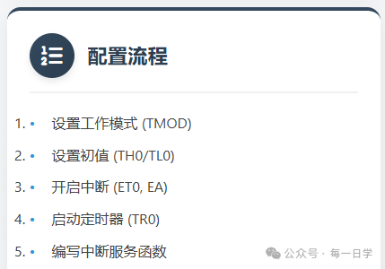
3. Hands-on configuration: Just use two “switch panels” 🔧
There’s no need to remember complex registers; think of them as the “switch panels for the timer”. Beginners only need to remember two core ones:
(1) TMOD panel: Set how the timer “works”
For example, if you want timer 0 to use “mode 1 + timing”, just set this panel: <span><span>TMOD = 0x01;</span></span> 👉 Explanation: 0x01 is hexadecimal, meaning “timer 0 (T0) is set to mode 1, timing mode”. If you want timer 0 to use “mode 1 + counting”, set:<span><span>TMOD = 0x05;</span></span> (adding a “counting” switch)
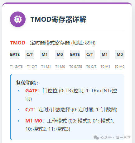
// Configure T0 as mode 1, timer, non-gated TMOD = 0x01; // Configure T1 as mode 2, timer, non-gated TMOD = 0x20;(2) TCON panel: Control “switches” and “states”
This panel has two key buttons:
-
🔘 Start switch (TR0/TR1):
<span><span>TR0=1;</span></span>means “turn on timer 0”,<span><span>TR0=0;</span></span>means turn it off -
💡 Overflow light (TF0/TF1): When the timer reaches the set time, this light turns on (TF0=1), and you need to manually turn it off after processing (
<span><span>TF0=0;</span></span>)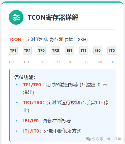
// Start timer 0 TR0 = 1; // Check if timer 0 has overflowed if(TF0 == 1) { // Handle overflow TF0 = 0; // Software clear flag}4. Practical case 1: LED blinks once every second (a must-learn for beginners)
After learning the theory, let’s jump straight to runnable code! Attached are the wiring diagram and key explanations, just burn it and use it~
// Complete configuration example void Timer0_Init() { TMOD &= 0xF0; // Clear T0 control bits TMOD |= 0x01; // Set T0 to mode 1 TH0 = 0xFC; // Set timer initial value high byte TL0 = 0x18; // Set timer initial value low byte ET0 = 1; // Enable T0 interrupt EA = 1; // Enable global interrupt TR0 = 1; // Start T0} // Interrupt service function void Timer0_ISR() interrupt 1 { TH0 = 0xFC; // Reload initial value TL0 = 0x18; // User code}(1) First, look at the wiring (super simple, done in 1 minute)
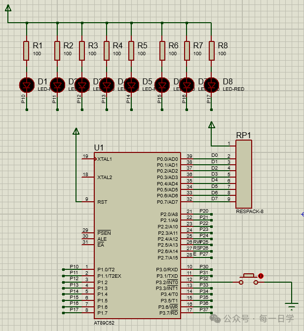
Microcontroller P1.0 pin → 220Ω resistor → LED anode → LED cathode → microcontroller GND) 👉 Reminder for beginners: Don’t skimp on the resistor, or the LED will burn out!
(2) Code (just copy and use, key parts are commented)
#include <reg52.h> // Common library for microcontrollers, must include // Define LED pin: P1.0 connected to LED sbit LED = P1^0; // Counter: accumulate timer interrupt counts unsigned int count = 0; // Step 1: Initialize timer 0 (like setting an alarm) void Timer0_Init() { TMOD = 0x01; // Timer 0: mode 1 + timing TH0 = 0x3C; // Initial value high byte (corresponds to 50ms timing) TL0 = 0xB0; // Initial value low byte (corresponds to 50ms timing) ET0 = 1; // Open timer 0 interrupt switch EA = 1; // Open global interrupt (key! Otherwise, the alarm won't wake the microcontroller) TR0 = 1; // Start timer 0 (press the alarm switch)} // Main function: the microcontroller executes here on startup void main() { Timer0_Init(); // Call initialization function, set the alarm while(1) { // Main loop: the microcontroller stays here "on standby" // Other code can be added here, like reading buttons, without affecting LED blinking }} // Step 2: Interrupt service function (when the alarm rings, execute here) void Timer0_ISR() interrupt 1 { TH0 = 0x3C; // Reload initial value (mode 1 needs manual loading, otherwise the next timing will be inaccurate) TL0 = 0xB0; count++; // Increment count every 50ms // 50ms×20=1000ms (1 second), when the time is up, toggle LED if(count == 20) { count = 0; // Reset count, start over LED = ~LED; // Toggle LED state (on→off, off→on) }}<code><span><span>(3) Effect preview</span></span>
After burning the code, the LED will blink precisely once every second, even if you add “read button” code in the main loop, the LED won’t blink erratically—this is the power of timers + interrupts!

5. Practical case 2: Counting mode (counting button presses)
Want to know how many times the button has been pressed? Using counting mode is super simple~
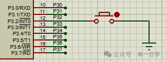
(1) Wiring
(2) Core code (only change initialization and interrupt function)
// Initialization function: change to counting mode void Timer0_Init() { TMOD = 0x05; // Timer 0: mode 1 + counting (key!) TH0 = 0xFF; // Initial value high byte (counts 5 overflows) TL0 = 0xFB; // Initial value low byte (0xFFFB to 0xFFFF is 5 times) ET0 = 1; // Open interrupt EA = 1; TR0 = 1; // Start counting} // Interrupt service function: LED toggles every 5 button presses void Timer0_ISR() interrupt 1 { TH0 = 0xFF; // Reload initial value TL0 = 0xFB; LED = ~LED; // Toggle LED every 5 button presses}6. Beginner’s Pitfall Guide (super important!) 💡
Always enable global interrupt (EA=1)
Many people can’t get their code to run because they missed this line—it’s like “not connecting the phone line, the delivery call can’t come in”.
Mode 1 requires manual reloading of the initial value
After the timer reaches the set time, the initial value will reset to zero, and you need to reassign it (like in the example<span><span>TH0=0x3C; TL0=0xB0;</span></span>), otherwise the next timing will take longer.
Don’t write too much code in the interrupt function
Interrupts are for “urgent tasks”; for example, only write “toggle LED” or “count”—don’t put loops in there—otherwise, the microcontroller will keep processing interrupts, and the main program will freeze.
After reading this, don’t you think “it’s that simple”? 👉 What else do you want the microcontroller to do? For example, “control a small motor” or “make a stopwatch”—let me know in the comments, and I’ll teach you next time!
If this article helped you, don’t forget to like + share it with friends learning microcontrollers together~ See you next time!