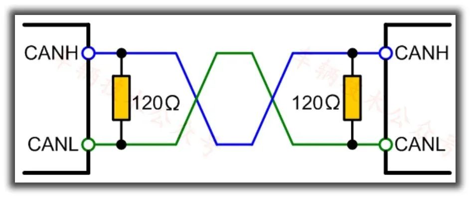
| Friends in “Vehicle Technology” should know that the CAN bus requires two 120 Ohm termination resistors at both ends, making the total line resistance 60 Ohms. |
This is a piece of knowledge that almost everyone knows, but very few can explain clearly.
In most cases, we have the experience that adding a 120 Ohm resistor allows messages to be sent, while removing the resistor prevents messages from being sent. Therefore, we have become accustomed to simply adding a 120 Ohm resistor to enable communication.
It seems so routine, just like brushing your teeth or using the restroom every morning; once you get used to it, you no longer care about the reasons behind it…

But why is this the case? Today, we will delve deeper into this topic. Our approach is:To observe the waveform!Because, most of the time, when the bus resistance is 40, 80, or even 30 Ohms, messages can still be sent. However, this does not mean that the network reliability is the same; we must let the waveforms speak for themselves.
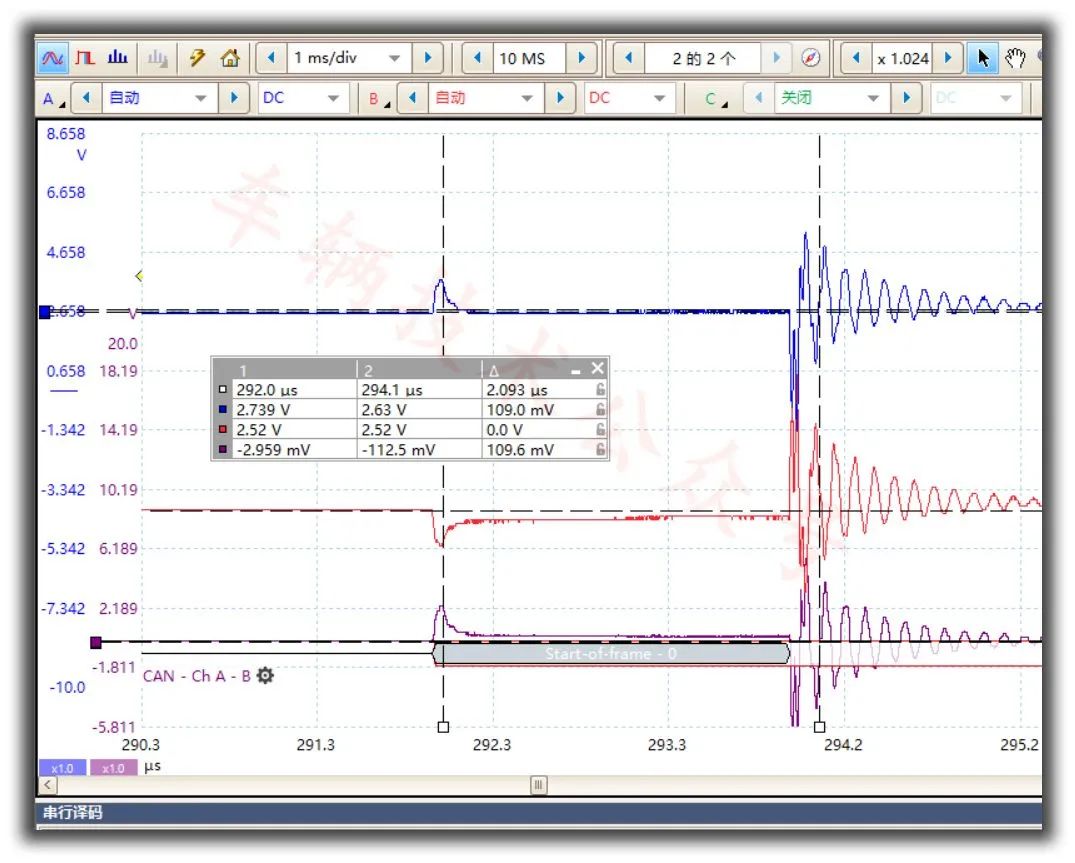
First, let’s look at a correct waveform

Here is a standard waveform with 120 Ohm resistors connected at both ends, as shown in the figure below:
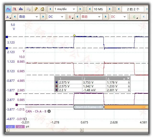
Look at how elegant and standard it is! More elegant than a teacher’s wife…
Look at its steep peaks, its calm plateaus, and its 2.3V differential voltage; it is simply textbook excellent!
At this point, we have only seen what a correct CAN message looks like. Next, we will analyze what an incorrect message looks like and why it is incorrect.
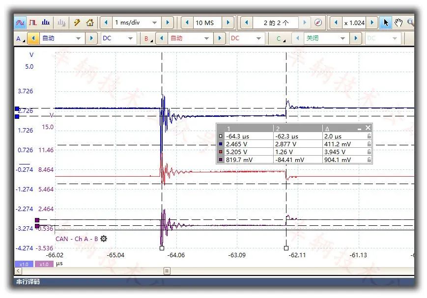
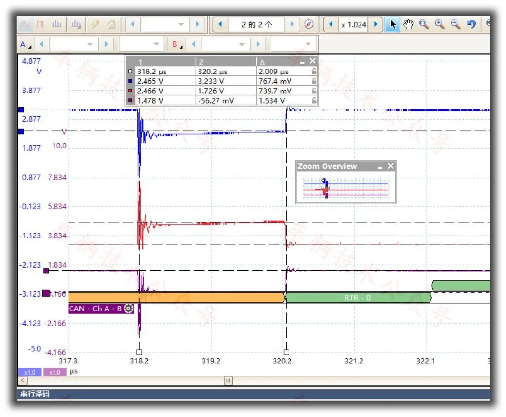
CAN message without termination resistors
Ta-da!
The following figure shows a CAN message waveform without termination resistors:
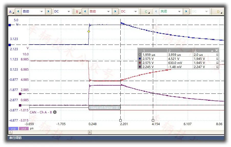
Now, the truth is revealed; we can clearly see why without termination resistors, messages cannot be sent!
For a bit, its rising edge is fine, still steep, but its falling edge has a significant problem; it cannot fall!

So, we need to pay attention to it and ponder why it cannot fall…According to Shizi No. 1, this is caused by the discharging effect of the RC circuit; at this time, the R value is basically the differential impedance of the CAN port, which is quite large.
Because the R value is too large, it cannot quickly dissipate the energy on the bus equivalent capacitance, resulting in a very flat discharge curve, and the voltage takes a long time to drop.Sending node corrupts the messageIn this experiment, our baud rate is 500k, and Shizi No. 1 set a time interval equal to one bit width. We can clearly see that at the end of the CANL bit width, the differential voltage is still as high as 2.247 volts, which will undoubtedly be treated as a transmission error by the sending node. I sent a recessive bit, why is it dominant on the bus? There must be a problem, and I need to report an active error!For the causes of error frames, please refer to the article below.Lecture 30 on the bus, regarding error frames, we need to address the causes rather than the error frames themselves.This is why, without termination resistors, CAN messages cannot be sent…The root cause has been found…Voltage too highAdditionally, we found that both the CANH voltage and the differential voltage are much higher than when using two 120 Ohm termination resistors. This is due to the current source effect of the circuit, but due to limited driving capability, it cannot maintain a constant current…
Let’s try a small resistor
Since a large resistor doesn’t work, can I make the resistor as small as possible?
Common sense tells us that this is definitely not possible; if it’s too small, it will short-circuit.
So, what happens when the resistor is relatively small? The following figure shows a waveform with a total bus resistance of 4 Ohms:
We can clearly see that the waveform has entered the PID control model; you can no longer see it as a digital waveform.

CANH, CANL, and differential voltages are all calm; the bus is completely paralyzed!
Its driving capability also determines that there cannot be any differential voltage at this time.
Let’s increase the resistance a bit
20 Ohms
Let’s try setting the total bus resistance to 20 Ohms:
Micro waveform
Macro waveform
I don’t know how other CAN cards perform, but with the CAN card I used from Tongxing, it was able to send and recognize messages normally at 20 Ohms. I wonder if this is considered excellent in the industry…
If you disagree, feel free to debate
However, the waveform at this point is clearly not reliable; it is already quite chaotic. When placed in a vehicle, if additional interference is added, it is very likely to cause problems!
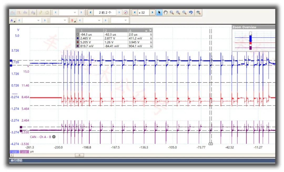
30 Ohms
Let’s try setting the total bus resistance to 30 Ohms:
Micro waveform
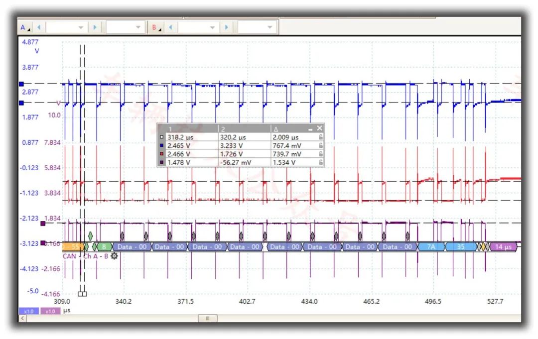
Macro waveform
The waveform at 30 Ohms is basically usable; it is likely recognizable by most CAN cards, as its differential voltage has reached 1.5V.
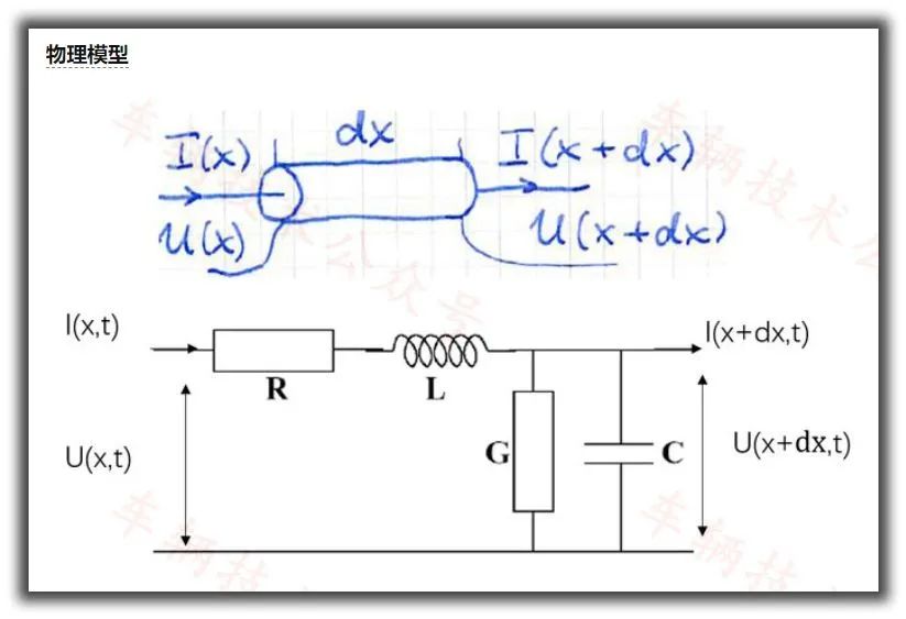
Why 120?
A great expert provided a theoretical derivation, as shown in the figure below.
After a series of complex formula derivations, the following conclusion was reached:
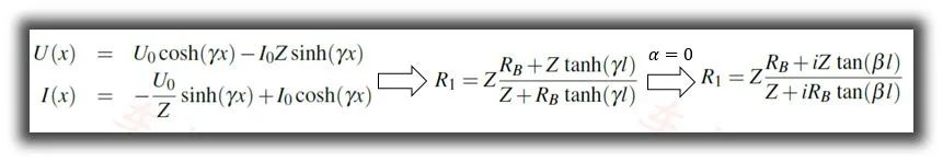
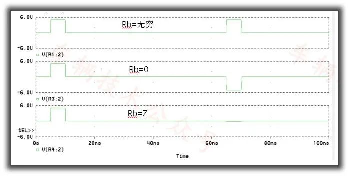
When Rb=Z, R1=Rb=Z, there is no reflection.
How to test the characteristic impedance of a CAN twisted pair?
Disconnect the twisted pair termination, measure its impedance with a multimeter in capacitance mode to get Z1; short the twisted pair, measure its impedance with a multimeter in inductance mode to get Z2.
Then the impedance Z of the twisted pair is the square root of Z1 multiplied by Z2.
| However, Shizi No. 1 really cannot understand this; for my level of knowledge, it is a bit beyond my grasp, and I have forgotten most of it.This should be the characteristics of cable signal transmission, but I don’t know if it applies to digital signals. |
Everyone talks about “signal reflection” and “impedance matching,” but I don’t quite understand the essence of what it means; what exactly is being reflected… I only know that both too large and too small resistances are not good; two 120 Ohm resistors are just right. Using the knowledge of Teacher Qiu Guanyuan to explain and extending it to the impact of resistance on waveforms, I find it more relatable.
【Recommended】