Requirements of High-Speed CAN Bus Physical Layer for Wiring Harness
Follow our public account, click the top right corner of the public account homepage ” ··· “, set a star, and stay updated on the latest news in intelligent automotive electronics and software.
Source: Automotive Electronics and SoftwareAuthor: Dou Mingjia
Currently, vehicles have more and more functions, including driving assistance functions such as 360-degree panoramic view, automatic parking, lane departure warning, lane keeping, ACC (Adaptive Cruise Control), front collision warning, reverse side warning, blind spot assistance, etc.; comfort functions such as air suspension, seat and mirror adjustment memory, etc. The realization of these functions relies on adding corresponding controllers. Moreover, the current controller design generally considers functional safety, with more sophisticated and complex control strategies. The number of signal interactions between corresponding controllers is also significantly increasing. These massive signals must rely on data transmission buses such as CAN, CANFD, MOST, FlexRay, and Ethernet, which is gradually being used. This article will briefly introduce the CAN2.0 protocol and its requirements for wiring harnesses based on the currently most widely used high-speed CAN bus.
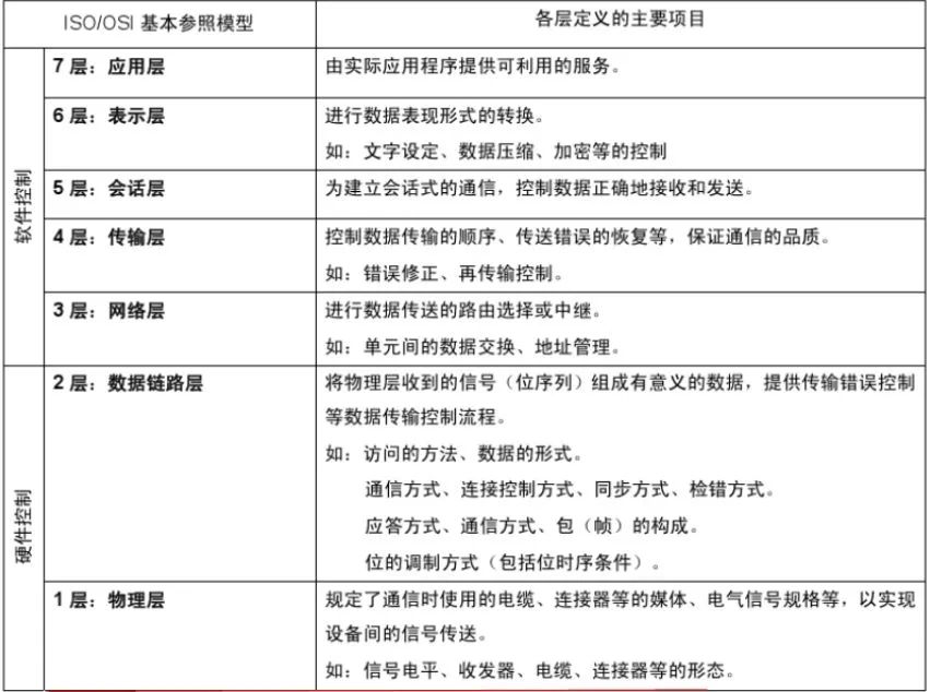
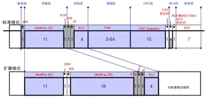
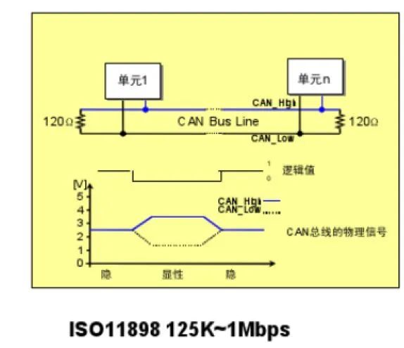
1. What is CAN?CAN (Controller Area Network) is a controller area network proposed by BOSCH to solve the increasing signal transmission in vehicles and is also an ISO international standardized serial communication protocol.Characteristics of CAN:① Multi-master control: Broadcast mode, where all units can send messages to the bus when the bus is idle. The message ID (identifier) priority is recognized through bitwise arbitration, with higher priority obtaining the right to send.② System flexibility: Units connected to the bus do not have information similar to an “address”. Therefore, when adding units to the bus, the hardware and software of other units connected to the bus do not need to change.③ Remote data request: Data can be requested from other units by sending a “remote frame”.④ Error detection, notification, and recovery functions: All units can detect errors. Detected errors will be immediately notified to all other units. If a unit sending a message detects an error, it will forcibly terminate the current transmission, and the unit that stopped sending will repeatedly resend until successful.⑤ Fault confinement: CAN can determine whether the error type is a temporary data error on the bus or a persistent data error (such as internal unit faults, driver faults, disconnections, etc.). When a persistent data error occurs on the bus, the faulty unit can be isolated from the bus.⑥ Connection: The number of units connected to the bus is limited by the time delay and electrical load on the bus. Reducing communication speed increases the number of connectable units, while increasing communication speed decreases the number of connectable units.2. OSI Basic Reference ModelCommunication protocols usually categorize related communication tasks by layers, allowing for greater flexibility in the application of bus systems.Hardware and software of CAN are divided into multiple layers:① Application Layer: Displays information in application data structure. This data is transmitted to the object layer.② Object Layer: Manages messages. The object layer decides when to send those messages and performs reception checks on received messages.③ Transport Layer: The transport layer transmits messages to the object layer and converts the messages obtained from the object layer into a form that the physical layer can send. Additionally, the transport layer is responsible for arbitration or error identification and marking.④ Physical Layer: The lowest layer, composed of physical network components such as wires and voltage.3. Message FormatCAN supports two different message formats, defined in CAN2.0A and CAN2.0B. The identifier of CAN2.0A has 11 bits, while the identifier of CAN2.0B has 29 bits. Both have the same data frame format, consisting of frame start, arbitration field, control field, data field, CRC, ACK field, and frame end.4. Bus Transmission① Bus Logic States and EncodingCAN bus has two logic states, namely dominant and recessive. Dominant represents binary bit “0”, while recessive represents binary bit “1”. After receiving bus messages, the CAN transceiver converts the signal levels into logic states, namely the difference between CAN_H and CAN_L levels. Various interferences (such as electrical fire systems) affect both wires equally, and the resulting differential level can filter out common-mode interference.In high-speed CAN, when transmitting recessive state bits, both CAN_H and CAN_L levels are 2.5V. When transmitting dominant bits, the level on CAN_H is 3.5V, and the level on CAN_L is 1.5V.In low-speed CAN, when transmitting recessive state bits, the level on CAN_H is 0V, and the level on CAN_L is 5V. When transmitting dominant state bits, the level on CAN_H is 3.6V, and the level on CAN_L is 1.4V.
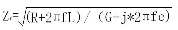
② Terminal Reflection EliminationOpen buses can generate terminal reflections that interfere with communication when transmitting electronic signals. To eliminate terminal reflections, a 120-ohm termination resistor is added at both ends of the bus.5. Requirements of CAN for Wiring Harness① Concept of Characteristic ImpedanceThe baud rate of the high-speed CAN bus is 500Kbit/S. At high frequencies, signals propagate through cables in the form of electromagnetic waves, and the resistance system and characteristic impedance of wires to electromagnetic waves are described at high frequencies.The characteristic impedance of a cable is the ratio of the electric field strength to the magnetic field strength transmitted in the cable (V/m)/(A/m)=ohms. The calculation formula for characteristic impedance is as follows:
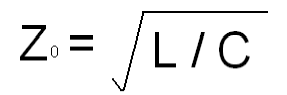
R = the resistivity of the conductor material (in DC conditions) per unit length, ohms; G = the conductivity of the insulation layer, ohms; J = imaginary number, +90-degree phase angle; Л = 3.1416; L = inductance per unit length of the cable; C = capacitance per unit length of the cable. At high frequencies, the two terms of f in the formula become very large, and R and G can be ignored. The formula simplifies to:
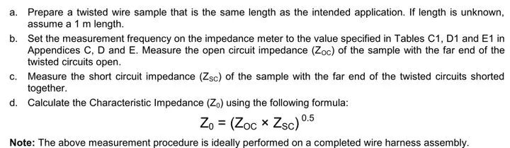
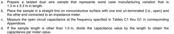
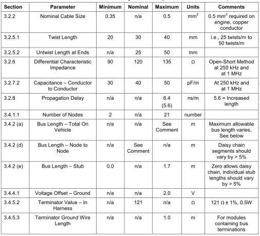
Therefore, at sufficiently high frequencies, characteristic impedance is not related to frequency, and characteristic impedance equals the square root of inductance/capacitance, which is the square root of the product of reactance and capacitive reactance.② Measurement Method of Characteristic ImpedanceThe characteristic impedance of a cable describes its working characteristics at high frequencies. A multimeter is used to measure resistance with direct current, so it cannot be used to measure the impedance of a cable. The characteristic impedance can be measured using specialized equipment by measuring the open-circuit impedance Zoc of a segment of cable at the far end, and then measuring the short-circuit impedance Zsc at the far end. The product of the two gives the characteristic impedance of the wire.③ Impedance MatchingIf there is a mismatch between the source output impedance, the cable’s characteristic impedance, and the load input impedance, there will be reflections. When these reflected waves collide with the signal generator (source), they mix with the normal signals being emitted, making it difficult to distinguish between the original signals and the reflected waves. Therefore, for high-speed CAN buses, the characteristic impedance of the cable is required to be 120 ohms.④ Capacitance Between Twisted PairsTo ensure the integrity of signal transmission, the capacitance between the wires of the CAN twisted pair must meet the requirements. The testing method is as follows:⑤ Propagation DelayTo ensure the real-time nature of signal transmission, the transmission time of signals on the cable must meet the requirements. The measurement method for signal delay is based on EIA-364-103. Below are the parameters required by a certain company for high-speed CAN bus cables.ConclusionIn addition to the above requirements, high-speed CAN also has requirements for wiring harnesses, such as the insulation layer of the wires, the twist rate of the twisted pair, the position of pins in connectors, and routing requirements (avoiding coaxial cables and signal lines that are easily affected, while avoiding high-current lines). When designing CAN wires, more consideration is given from the perspective of signal transmission theory, unlike other power and ground wires.
Follow our public account, click the top right corner of the public account homepage ” ··· “, set a star, and stay updated on the latest news in intelligent automotive electronics and software.
Disclaimer: The article represents the author’s independent views and does not represent the position of Wangcai Automotive Electronics. If there are issues regarding the content, copyright, etc., please contact Wangcai Automotive Electronics within 30 days of publication for deletion or copyright negotiation.