M-Bus Master to PROFIBUS DP Slave – adfweb Converter-HD67053
Author: Zou Wuyi Mobile185-020-77899 Email: [email protected]
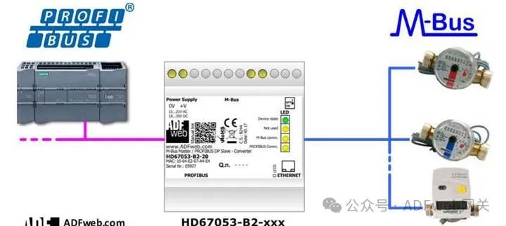
1 Product Features: “HD67053-B2-xxx” is a M-Bus Master Converter for converting between the PROFIBUS DP bus and the M-Bus . It has the following features:
- Electrical isolation between PROFIBUS and M-Bus ;
- Can be mounted on a 35mm DIN rail;
- Operating temperature range from -40°C to +85°C.
This converter can connect up to 250 standard M-Bus devices. The specific number of supported devices depends on the code represented by the “xxx” number:
- HD67053-B2-40 supports up to 40 M-Bus devices;
- HD67053-B2-80 supports up to 80 M-Bus devices;
- HD67053-B2-160 supports up to 160 M-Bus devices;
- HD67053-B2-250 supports up to 250 M-Bus devices.
For HD67053-B2-160:
- The device must be installed horizontally on a 35mm DIN rail mounted on the wall or cabinet backplane.
- To avoid affecting airflow around the device, it is recommended not to obstruct the air circulation path.
For HD67053-B2-250:
- The device must be installed horizontally on a 35mm DIN rail mounted on the wall or cabinet backplane.
- The device housing is equipped with a fan on the top. To avoid affecting airflow around the device, it is recommended not to obstruct the air circulation path and to ensure the fan is not blocked.
- It is recommended to install the device in a well-ventilated cabinet.
Configuration:
You need to install the Compositor SW67053 software on your PC to perform the following actions:
- Define the parameters for the PROFIBUS and M-Bus buses;
- Define the M-Bus devices on the bus and select the desired values;
- Create a GSD file to import into your PROFIBUS master;
- Update the device.
2 New Configuration / Open Configuration: The “New Configuration” button creates a folder containing the configuration for the entire device. The device configuration can also be imported or exported: To clone a programmable “M-Bus Master / PROFIBUS DP Slave – Converter” configuration to configure another device in the same way, the folder and all its contents must be retained; to clone a project for different versions of that project, simply copy the project folder to another name and open the new folder with the “ Open Configuration” button.
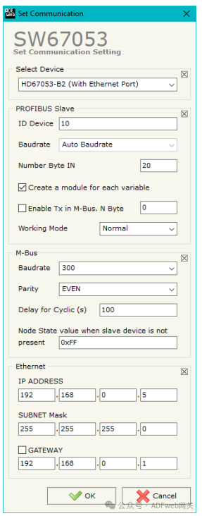
3 Setting Communication: This section defines the basic communication parameters for the two buses (PROFIBUS and M-Bus). Through the “ Set Communication” button in the main window (for SW67053, see Figure 2), the “ Set Communication” window will pop up (see Figure 3). This window is divided into three sections for PROFIBUS, M-Bus and Ethernet (if present).
In the “Select Device” section, you can define the hardware used:
- HD67053M;
- HD67053-B2 (without Ethernet port);
- HD67053-B2 (with Ethernet port).
PROFIBUS field meanings are as follows:
- In the “ Device ID” field, define the PROFIBUS end device ID;
- In the “ Baud Rate” field, define the PROFIBUS data rate (fixed to “ Auto Baud Rate”);
- In the “ Input Bytes” field, define the number of input bytes for PROFIBUS ;
- If checked, “Create a Module for Each Variable”, multiple modules will be created based on the number of variables defined in the “M-Bus” section; otherwise, a maximum of 64 byte module will be created;
- If checked, “ Enable Sending in M-Bus ”, you can send M-Bus frames by writing to the PROFIBUS output bytes;
- In the “ Output Bytes” field, define the number of output bytes for PROFIBUS ;
- If checked, “ Normal Mode”, PROFIBUS will use 244 bytes to store data from all M-Bus slaves; otherwise, if checked, “ Single Slave Mode”, all 244 bytes will be used to store data from a single slave (for more details, see the 33 page in the “ Single Slave Mode Function” section).
- M-Bus field meanings are as follows:
- In the “ Baud Rate” field, define the data rate for the M-Bus line;
- In the “ Parity” field, define the parity method for the M-Bus line;
- In the “ Cycle Delay (seconds)” field, define the time (in seconds) between two M-Bus scans;
- In the “ Node Status Value When Slave Device Does Not Exist” field, you can insert a value to be assigned to the “ Node Status” when the converter does not find the queried M-Bus slave device.
- “ Ethernet” section field meanings are as follows:
- In the “IP Address” field, define the IP address to be assigned to the converter;
- In the “ Subnet Mask” field, define the subnet mask to be assigned to the converter;
- In the “ Gateway” field, define the default gateway for the network. This function can be enabled or disabled by checking the checkbox field. This function is used to access external networks.
- These details are used to configure the converter.
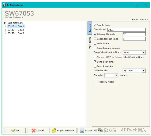
4 M-BUS Through the main window (for SW67053, see Figure 2) the “M-Bus” button can open the “M-Bus Network” window (see Figure 4). In the “ Node” section, you can create nodes for the M-Bus line: In the “ Description” field, you can enter a short description for the node.
Node Section (M-BUS Node): To create a new node, you need to select the address type to use, choose “ Master ID” or “ Slave ID” for the request, then insert the M-Bus device’s “ Master Address” (range from 1 to 250) or “ Slave Address” (range from 0 to 99999999).
- If the “ Node Status” field is checked, the gateway will retain a byte at the beginning of the internal data array and save the status of the counter.
- If the “ Identification Number” field is checked, the gateway will retain four bytes at the beginning of the internal data array and save the slave device’s address.
- If the “ Convert BCD to Integer Identification Number” field is checked, the converter will convert the identification number usually represented in BCD format to an integer.
- In the “ Swap Identification Number” field, you can select the swap mode for the identification number. If no swap is needed, select “ None”; otherwise, refer to the 29 page of this document for the “ Swap Identification Number” section to select the swap mode.
- If the “ Send SND_NKE” field is checked, the converter will send the “SND_NKE” frame to initiate communication.
- If the “ Send Application Reset” field is checked, the converter will send the “ Application Reset” command to the slave device.