
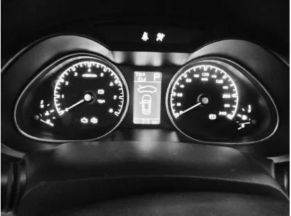
The most common fault symptom is an abnormal display on the dashboard, as shown in the figure below.
During the inspection process, the first step is to check the specific fault symptoms, and based on the fault symptoms and network structure diagram, to preliminarily analyze the possible causes. Then, use relevant diagnostic instruments for diagnosis, and formulate relevant repair plans based on the diagnostic results, ensuring clarity and defined objectives. Next, locate the specific fault location and cause, while combining appropriate detection methods and measurement results to find the fault point, thus thoroughly eliminating the fault.
Since the CAN network adopts multiple protocols, each control module’s port has standard voltages under normal circumstances. Therefore, the voltage measurement method can be used to determine if there are issues such as short circuits to ground or power, or short circuits between phase lines.
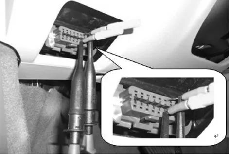
To determine whether the CAN H or CAN L wires are damaged or if the signals are normal, the ground voltage (average voltage) can be measured. The measurement point is usually at the OBD diagnostic interface, as shown in the figure below.
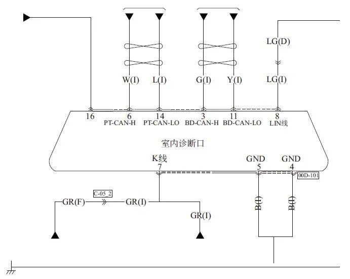
Pin 6 of the diagnostic interface is connected to the CAN H wire, and pin 14 is connected to the CAN L wire. If there are two sets of CAN buses connected at the diagnostic interface, the power CAN bus uses pins 6 and 14, while the comfort bus uses pins 3 and 11. The pin meanings of the diagnostic interface are shown in the figure below.
Under normal circumstances, when the CAN bus is awakened, the ground voltage of CAN H is about 2.656V, the ground voltage of CAN L is about 2.319V, and the sum of the two is 4.975V ▼
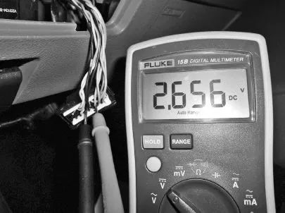
Normal CAN H voltage
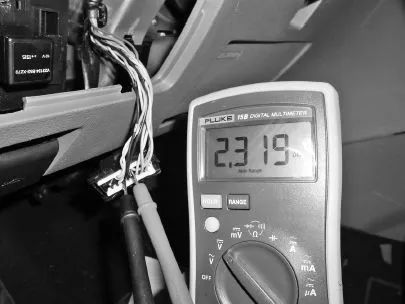
Normal CAN L voltage
Common causes of CAN faults include short circuits between CAN wires, short circuits to power, short circuits to ground, and reversed connections.
1. Short Circuit Between CAN H and CAN L
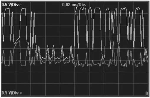
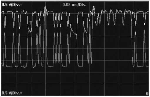
When CAN H and CAN L are short-circuited, the CAN network will shut down, and communication will no longer be possible. There will be corresponding network fault codes. The bus waveform of the short circuit between CAN H and CAN L is shown in the figure below.
After a short circuit occurs between the two, the CAN voltage position will be at a hidden voltage value (about 2.5V). Actual measurements of the voltages of the two CAN wires will show that it remains around 2.5V, with little variation, as shown below.
Troubleshooting Method: By unplugging the control modules (nodes) on the CAN bus, it can be determined whether the short circuit is caused by a node or by a wire connection.
Disconnect each node one by one; if the voltage returns to normal, it indicates that there is a problem with that node. If the voltage still does not change after disconnecting all nodes, it indicates a wire short circuit.
2. Short Circuit of CAN H to Power (Positive)
When a short circuit occurs from CAN H to power (positive), due to the fault tolerance characteristics of the CAN bus, the entire CAN network may be unable to communicate or generate related fault codes.
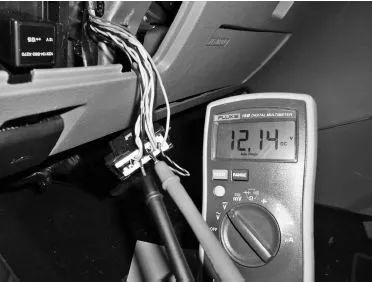
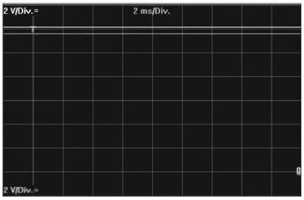
Taking a short circuit to a 12V power supply as an example, at this time the CAN H voltage level is set to 12V, and the hidden voltage of the CAN L wire is set to approximately 12V. The bus waveform of CAN H shorted to power is shown in the figure below.
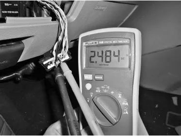
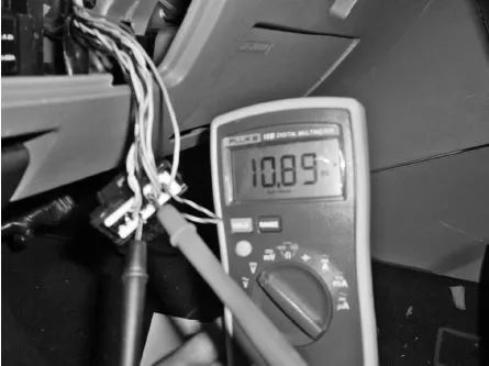
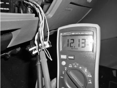
When measuring voltage, if the CAN H voltage is 12V and the CAN L voltage is approximately 11V, it indicates that this type of fault has occurred. The CAN H voltage in the short circuit to power is shown in the figure below.
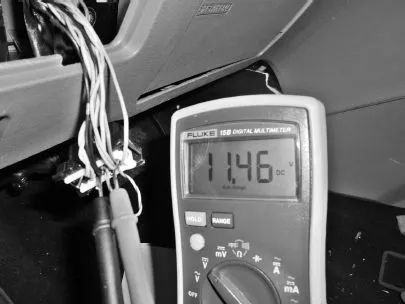
The CAN L voltage in the short circuit to power is shown in the figure below.
Fault Cause: If the short circuit is not caused by the CAN H wire to the external power supply, then this fault may be caused by a damaged CAN transceiver inside the control module. The fault finding method is the same as above.
3. Short Circuit of CAN H to Ground
When a short circuit occurs from CAN H to ground, due to the fault tolerance characteristics of the CAN bus, the entire CAN network may be unable to communicate or generate related fault codes.
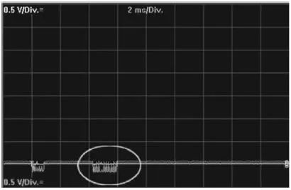
The voltage of CAN H is at 0V, and the voltage of CAN L is also at 0V, but a small amount of voltage variation can still be seen on the CAN L wire. The bus waveform of CAN H shorted to ground is shown in the figure below.
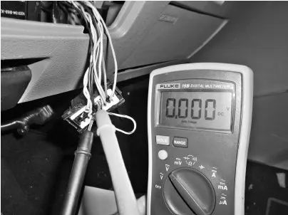
When measuring voltage, if both CAN H and CAN L voltages are approximately 0V, and there are no open circuit issues, it indicates that this type of fault has occurred. The CAN H voltage in the short circuit to ground is shown in the figure below.
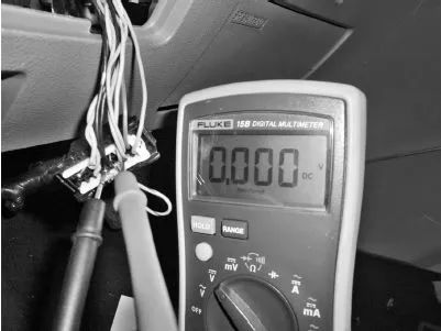
The CAN L voltage in the short circuit to ground is shown in the figure below.
Fault Cause: If the short circuit is not caused by the CAN H wire to the external ground, then this fault may be caused by a damaged CAN transceiver inside the control module. The fault finding method is the same as above.
4. Short Circuit of CAN L to Ground
When a short circuit occurs from CAN L to ground, due to the fault tolerance characteristics of the CAN bus, the entire CAN network may be unable to communicate or generate related fault codes.
However, for certain vehicle series, such as Haima, the fault tolerance characteristics of CAN L shorted to ground are relatively good, and the vehicle can generally operate normally, meaning there are no significant abnormal phenomena from the customer experience perspective, but from a diagnostic standpoint, it will affect network transmission speed.
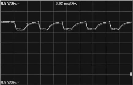
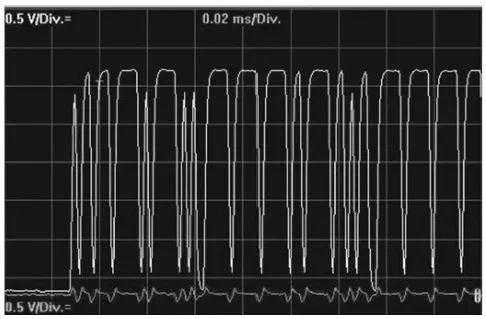
At this time, the CAN L voltage is approximately 0V. The hidden voltage of the CAN H wire is reduced to 0V, but the explicit voltage remains basically unchanged, so the waveform is elongated, still allowing data transmission. This explains the good fault tolerance characteristics of CAN L shorted to ground. The bus waveform of CAN L shorted to ground is shown in the figure below.
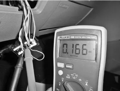
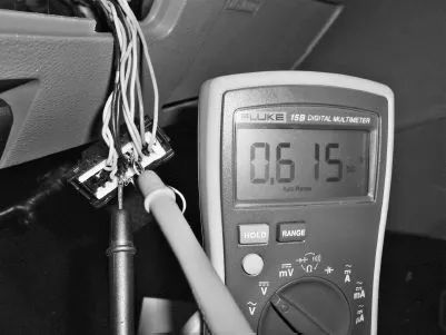
When measuring the voltage of the CAN wires, if the CAN L voltage is 0V and the CAN H voltage is around 1V, it indicates that this type of fault has occurred. The CAN L voltage in the short circuit to ground is shown in the figure below.
The CAN H voltage in the short circuit to ground is shown in the figure below.
Fault Cause: If the short circuit is not caused by the CAN L wire to the external ground, then this fault is caused by a damaged CAN transceiver inside the control module. The fault finding method is the same as above.
5. Short Circuit of CAN L to Power (Positive)
When a short circuit occurs from CAN L to power (positive), due to the fault tolerance characteristics of the CAN bus, the entire CAN network may be unable to communicate or generate related fault codes.
Since CAN L is shorted to power, the CAN H voltage is also set to 12V. The bus waveform of CAN L shorted to power is shown in the figure below.
When measuring the voltage of the CAN wires, if both CAN L and CAN H wire voltages are approximately 12V, it indicates that this type of fault has occurred. The CAN L voltage in the short circuit to power is shown in the figure below.
The CAN H voltage in the short circuit to power is shown in the figure below.
Fault Cause: If the short circuit is not caused by the CAN L wire to the external power supply, then this fault may be caused by a damaged CAN transceiver inside the control module. The fault finding method is the same as above.
6. CAN H Open Circuit
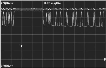
When a control module’s CAN H wire is open-circuited, it will cause that control module to be unable to communicate, but communication with other control modules is still possible. Other control modules may read the fault code of the faulty module. If multiple control modules have open-circuited CAN H wires, then the communication functions of those control modules will all be affected. The bus waveform of CAN H open circuit is shown in the figure below.
If the faulty control module has a terminal resistor, the resistor measurement method can be used to determine. Measure the resistance between CAN H and CAN L at the diagnostic interface; if it changes to 120Ω, it indicates that a terminal resistor is open. If the faulty control module does not have a terminal resistor, then the continuity of the CAN wire of that control module needs to be measured.
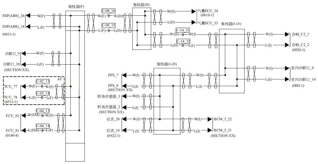
Replacing the control module that has the fault code content can quickly determine whether the fault is caused by that control module itself. Additionally, it is necessary to refer to the network diagram to find the breakpoints, as the corresponding bus hubs will be set in the entire network; different breakpoints will affect different components and will also determine which control modules can be diagnosed by the diagnostic instrument. The distribution of the CAN network and hubs is shown in the figure below.
7. CAN L Open Circuit
When a control module’s CAN L wire is open-circuited, it will cause that control module to be unable to communicate, but communication with other control modules is still possible. Other control modules may read the fault code of the faulty module. If multiple control modules have open-circuited CAN L wires, then the communication functions of those control modules will all be affected.
If the faulty control module has a terminal resistor, the resistor measurement method can be used to determine. Measure the resistance between CAN H and CAN L at the diagnostic interface; if it changes to 120Ω, it indicates that a terminal resistor is open. If the faulty control module does not have a terminal resistor, then the continuity of the CAN wire of that control module needs to be measured. The bus waveform of CAN L open circuit is shown in the figure below.
Replacing the control module that has the fault code content can quickly determine whether the fault is caused by that control module itself. Additionally, it is necessary to refer to the network diagram to find the breakpoints, accurately determining the cause and eliminating the fault.
8. Reversed Connections of CAN L and CAN H Wires
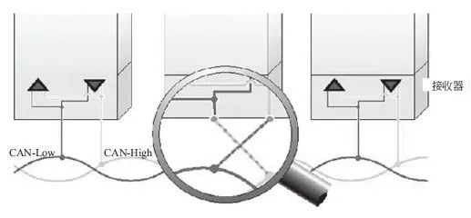
When a fault occurs with the CAN L and CAN H wires reversed, generally, the control module that is incorrectly connected will be unable to communicate, while communication with other control modules remains normal. The schematic diagram of the reversed connections of CAN L and CAN H wires is shown in the figure below.
Measure the voltage at the CAN wire pins of the suspected faulty control module to verify whether the voltage is normal. Check the wiring connections against the CAN network diagram to determine if this fault exists. If it does, repair the CAN network. Replacing the control module that has the fault code content can also help determine whether the fault is caused by that control module.
Notice: The Wiring Harness Engineer WeChat Mini Program has been launched,Click to access the “Wiring Harness Engineer” WeChat Mini Program

Scan to ↑ ↑ ↑Follow the Video Account
| Wiring Harness Engineer Learning and Improvement Material Package (Click to Directly Access) | |
| System Improvement Essentials | CATIA Wiring Harness Design |
| CHS Wiring Harness Design | Whole Vehicle Schematic Application |
▲ Click to Follow, Reply “Resources” to receive a 10G wiring harness design material package!Reply“Join Group” to join the Wiring Harness Engineer Technical/Resource Group!