↑ Click the above “Chinese Surveying and Mapping Society“
to quickly follow us
Marine research, marine engineering construction, military activities, and resource surveys are all based on ocean environmental monitoring, especially for long-term, fixed-point, real-time, and three-dimensional monitoring of the marine dynamic environment. Seabed-based and buoy observation systems operate underwater, featuring good concealment and long maintenance cycles, used for fixed-point marine environmental monitoring. Since seabed-based and buoy observation systems typically integrate many expensive measuring instruments and store a large amount of valuable data, one of the key considerations before deployment is how to ensure reliable recovery of the system later. To address this issue, scientists have integrated beacon machines into the observation systems that need to be deployed underwater, serving as positioning tools during recovery operations, and also providing alerts when the system unexpectedly surfaces due to damage.
A beacon machine is a device that can transmit specific identification signals to the outside world. Once the activation conditions are met, it automatically sends radio or positioning signals that can be detected externally. Early beacons primarily emitted radio signals. After the observation system surfaced, the beacon signal could be detected within a certain range, allowing recovery personnel to determine the beacon’s position based on the strength of signals from various directions. However, this method could not obtain the exact latitude and longitude of the target, and the communication range was often limited to about 10 nautical miles. With the development of mobile internet and satellite networks, the new generation of beacon products has integrated positioning chips and satellite transmission antennas. When the observation system surfaces, the beacon can transmit its precise location to receivers or fixed network addresses via the internet. Recovery personnel can then go directly to the target marine area to complete the recovery operation. Table 1 shows a list of mature beacon products available on the market.
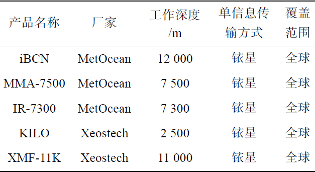
Table 1 List of Mature Beacon Products Internationally
With the expansion of marine observation ranges, all mainstream beacon products worldwide now use the global Iridium satellite system as the signal transmission medium, capable of serving underwater observations in deep oceans and polar regions. Most beacons are equipped with pressure sensors, using water pressure values as activation signal switches. Before deployment, the beacon is fixed to the top structure of the observation system, activating a physical or electromagnetic switch, placing the beacon in working status. After being submerged, when the internal pressure sensor detects a water pressure value greater than the pre-set value (usually less than 1 dbar), the beacon stops working and continues to descend with the observation system to a certain depth for long-term fixed-point observation. During the recovery phase, as the observation system rises and the beacon surfaces, when the water pressure value measured is less than the set value, the beacon starts working and sends location signals. The terminal can quickly locate the observation system that needs to be recovered after obtaining the coordinates sent by the beacon machine.
Although the above products can be used in global waters, they are expensive and consume a lot of energy during the satellite search and signal transmission process. Therefore, they are mainly applied in high-cost complex observation systems deployed in deep oceans. For some nearshore or low-cost observation carriers, low-power beacon products that meet the positioning and communication needs of the observation area are more competitive. This paper focuses on underwater fixed-point observation in China’s offshore waters, designing a low-power, low-cost marine positioning beacon with a unique activation method based on the BeiDou and mobile telecom networks, primarily serving marine ranch construction, coastal engineering, and nearshore marine dynamic process research.


Unlike the mainstream activation methods of current beacons, the beacon mentioned in this paper completes its operational conversion through electrode short-circuiting and open-circuit operations. The beacon system consists of a beacon transmitter and beacon reception software. The beacon transmitter includes a control module, power module, and antenna module; the reception software has terminal display functions, target positioning functions, and information prompt functions. The overall system composition is shown in Figure 1.
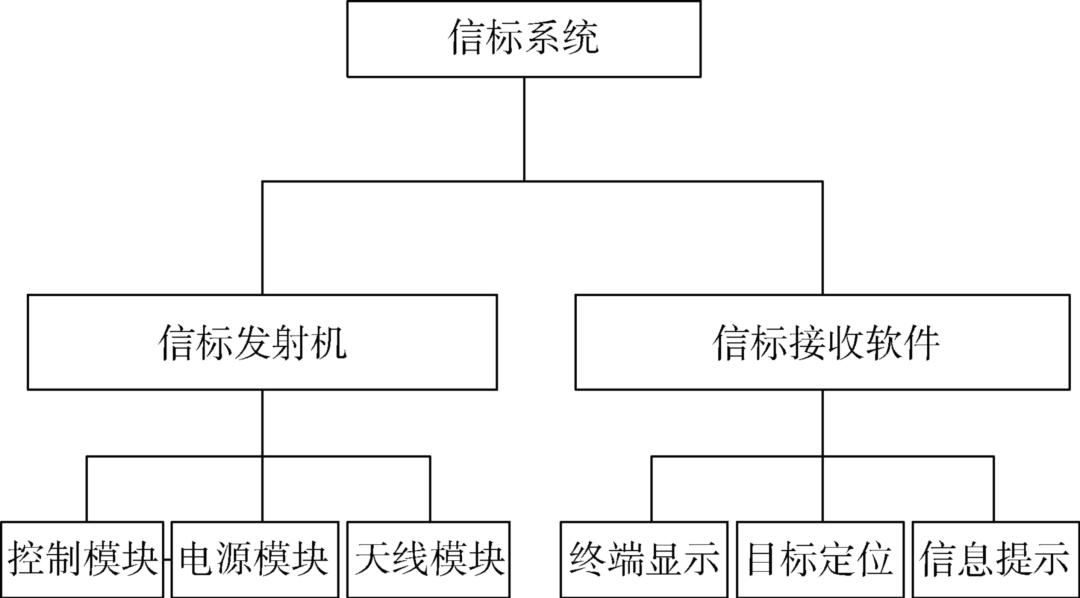
Figure 1 Composition of the Beacon System
The beacon machine is structurally divided into a top end cap, electrodes, main body, main board, battery, and bottom end cap. The outer shell of the beacon machine includes two end caps and a main body, made from polytetrafluoroethylene (PTFE). The main body adopts a cylindrical structure, which helps to reduce the resistance of seawater against the body, has good radial pressure resistance, and is easy to process. The top end cap has two metal electrodes on the outside, used to trigger the internal control circuit.
The main body is designed with four sets of series battery compartments, each 28 cm in length, with a single battery needing to meet the appearance standards of a D-type standard No. 1 battery, which is 59.0 mm ± 0.5 mm in height and 32.3 mm ± 0.2 mm in diameter. The beacon machine is designed to require a voltage input of 9-18V, thus using four FANSO34615 model 3.6V lithium batteries in series to form a 14.4V battery pack as the power supply. The resistance of the internal pressure sensing spring in the battery compartment cannot be too high, or it will cause the battery output voltage to fail to meet the system’s power supply requirements. The overall structural design diagram and physical diagram of the beacon machine are shown in Figure 2, with the left side being the design diagram and the right side being the physical diagram.
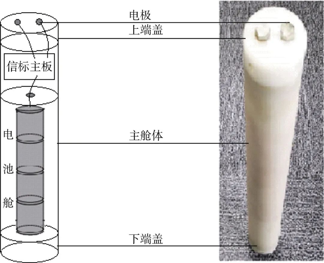
Figure 2 Design Diagram and Physical Diagram of the Beacon Machine
The main board of the beacon machine includes a power socket, microcontroller, GSM card slot, signal antenna, etc. The startup control circuit board is designed separately and is connected to the main board and the upper end cap electrodes through a feeder. The main board is designed to be compact, measuring 5 cm in length and 2 cm in width, much smaller than the inner diameter of the shell, and is fixed inside the shell through a support. Its power control chip meets the wide voltage input standard of 9-18V. The design diagram of the main board is shown in Figure 3.
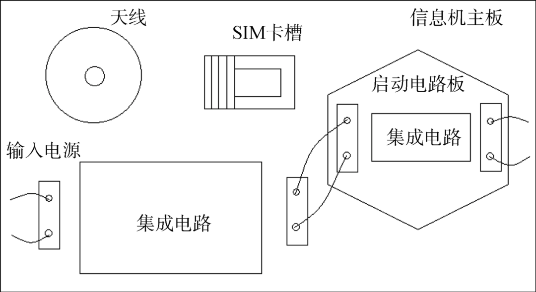
Figure 3 Design Diagram of the Main Board of the Beacon Machine
The control module integrates a GPS antenna, SIM card slot, and includes an integrated circuit with a programmable controller, condition activation circuit, and working sequence that can be read and set through software. The programmable controller uses a mature GPS navigation positioning control component, and the positioning antenna uses a mature T102 GPS module, with positioning accuracy within 2.5m. The introduction of the condition activation circuit is an innovation that distinguishes this beacon machine from traditional beacon machines, and its circuit design diagram is shown in Figure 4.
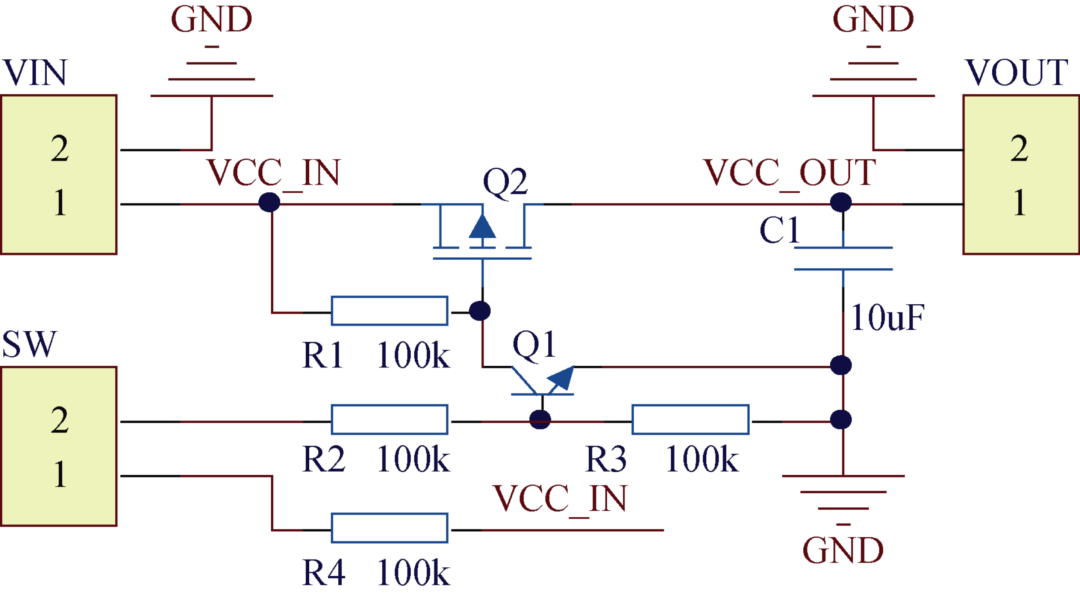
Figure 4 Condition Activation Circuit Design Diagram
The condition activation circuit utilizes various dissolved electrolytes in water to generate a large number of free charged ions. Under an external electric field, the charged ions move directionally, thereby exhibiting conductivity. The SW interface connects two external conductive electrodes, VIN connects to the battery (1 connects positive, 2 connects negative), and VOUT connects to the power supply of the beacon machine main board (1 connects positive, 2 connects negative). In the circuit, R2, R3, and R4 form the water conductivity detection circuit, while R2 and R3 form a current-limiting voltage divider circuit to drive the transistor Q1 to conduct. Before entering the water, the two external conductive electrodes connected to SW are not conductive, and R2 and R3 are grounded with no current, keeping the transistor off; after entering the water, due to the conductivity of the water, current flows from R4 through the two external conductive electrodes of SW, passing through R2 and R3 to generate voltage and current, driving the transistor to conduct. The transistor Q1, PMOS transistor Q2, and R1 form the power switch circuit, controlling the on/off of power from VIN to VOUT, with current flowing from VIN to VOUT. When transistor Q1 conducts, it drives PMOS transistor Q2 to conduct, turning on the power supply connected to VOUT of the beacon machine main board. When transistor Q1 is off, PMOS transistor Q2 is off, turning off the power supply connected to VOUT. The capacitor C1 serves to filter noise and AC components from the power supply after VOUT is turned on. The final effect is that when there is no conductor connected across the electrodes, i.e., when the electrodes are in the air at the sea surface, the beacon is in the working startup state; when a conductor is connected across the electrodes, i.e., when the electrodes are in conductive seawater, the beacon is in the working stop state.
The design introduces a condition activation circuit, allowing the beacon machine to no longer require pressure sensors, thus saving on overall procurement and manufacturing costs. Additionally, the beacon machine does not need to keep its internal power and clock on to continuously read real-time pressure sensor values, saving on power supply costs. Finally, the working state of the beacon machine relies on the conductive state of the external electrodes to switch, avoiding the use of relays, reducing an intermediate link, and lowering the control costs of the timing circuit. The introduction of the condition activation circuit overall reduces system power consumption and costs. A comparison of functions between traditional beacon machines and the designed beacon machine is shown in Table 2.
|
Information |
Traditional Beacon Machine |
Designed Beacon Machine |
|
Activation Method |
Perceiving External Water Pressure Value |
Perceiving External Conductivity Value |
|
Internal Pressure Sensor |
Required |
Not Required |
|
Working State Switching Relay |
Required |
Not Required |
|
Data Acquisition Circuit Working State |
2 channels of data acquisition, one continuously collects external pressure value; the other controlled to collect positioning signals |
1 channel of data acquisition; controlled to collect positioning signals |
|
Power Supply Mode Underwater Observation |
Continuous Power Supply |
Condition Controlled Power Supply |
Table 2 Comparison of Functions with Traditional Beacon Machines
The receiving unit consists of a cloud server and browser. GSM signals can be directly sent to the cloud, and a B/S system architecture terminal receiving system is developed to achieve cloud storage, allowing for batch querying and management of beacon locations as needed. The significance of establishing a cloud receiving system is that it enables users to conveniently log into the interface from anywhere with internet access to check the status of the beacon machine, while simultaneously tracking and managing its location trajectory. The receiving unit mainly consists of terminal display, target positioning, and information prompt function modules, with detailed explanations of each module’s functions as follows.
⑴ The terminal display module is responsible for displaying and updating the beacon machine number, firmware version information, and real-time latitude and longitude location information. The web program interface integrates an embedded map component, allowing users to select the beacon machine number they wish to query, presenting the most recent location information of the beacon on the map, and enabling the display of the beacon’s movement trajectory over a period, facilitating the tracking of its location by equipment recovery personnel.
⑵ The target positioning module is responsible for displaying the real-time relative position of the target beacon machine to the receiving terminal. Through this module, equipment recovery personnel can clearly obtain information about the direction and distance of the beacon machine relative to themselves, guiding the rapid implementation of target search operations.
⑶ The information prompt function module is responsible for warning displays of the target beacon machine’s status. By comparing pre-set voltage thresholds and location ranges, once the voltage of the beacon machine falls below the threshold, the terminal will prompt an energy alert; once the beacon machine’s real-time return location is outside the pre-set distance from the deployment location.
The overall architecture of the receiving end is divided into client and web service end. The client can be a browser or mobile app, while the web service end uses the Express framework and SQLServer database to store the beacon data and user data transmitted over the network. The overall architecture of the receiving end is shown in Figure 5.
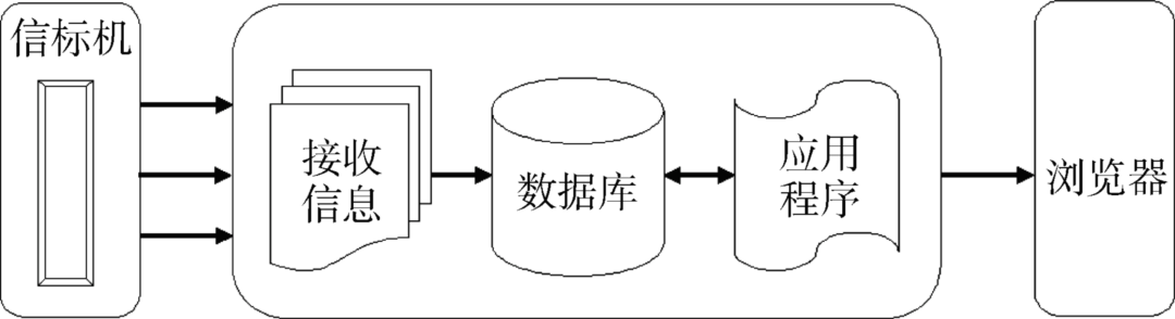
Figure 5 Overall Architecture of the Receiving End


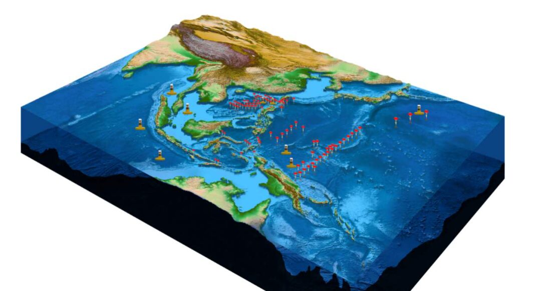
To test the actual positioning performance of the beacon machine and its communication conditions at different locations, on January 3, 2020, testing personnel carried the developed beacon aboard a vessel from Weihai to conduct a beacon function testing experiment at 12 stations. The weather conditions on that day were good, sunny, with a light breeze and sea conditions at level 2. The beacon was fixed to the upper part of the observation buoy system, and each time the buoy body surfaced, the beacon machine was in the air, successfully sending location information.
Among the 12 test stations, the nearest station was by the shore, and the farthest station was 36.7 km away from the shore. The entire test sea area, test route, and stations were clearly presented on the receiving end software. The total time from departure to return was 500 minutes, with the beacon placed underwater for testing at each station for 5 minutes, totaling 60 minutes of underwater testing, during which no receiving signals were detected; the surface testing (including travel time) totaled 400 minutes, with 216 minutes of surface testing at the 12 stations, during which location signals were received. The station test information is shown in Table 3.
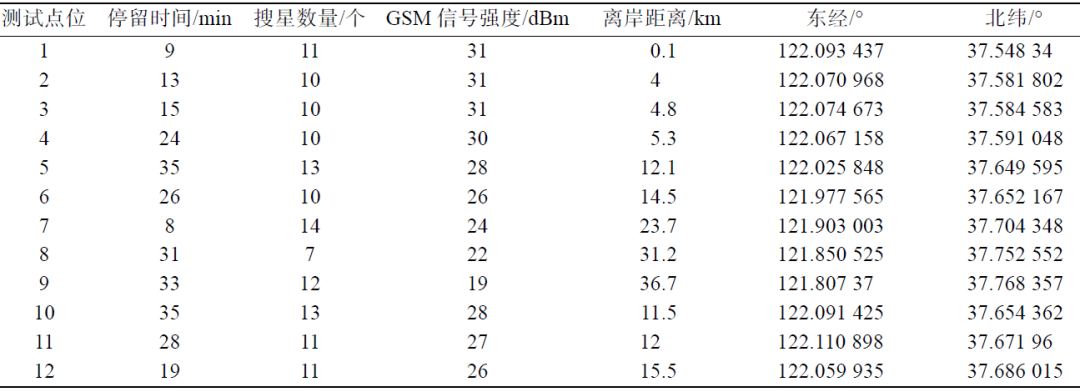
Table 3 Test Information for Each Station
As shown in Figure 6, the number of positioning satellites acquired by the beacon at each experimental station and the signal strength varied significantly. At the station closer to the shore, the number of satellites searched was greater, with a maximum of 14, and the signal strength was generally strong, reaching a maximum of 31 dBm; at the station farther from the shore, the number of satellites searched was fewer, with a minimum of 7, and the signal strength was generally weak, with a minimum of only 19 dBm. This situation is primarily related to the location of the base stations; since most base stations are built on land, the beacon’s positioning ability will weaken in areas far from the coast.
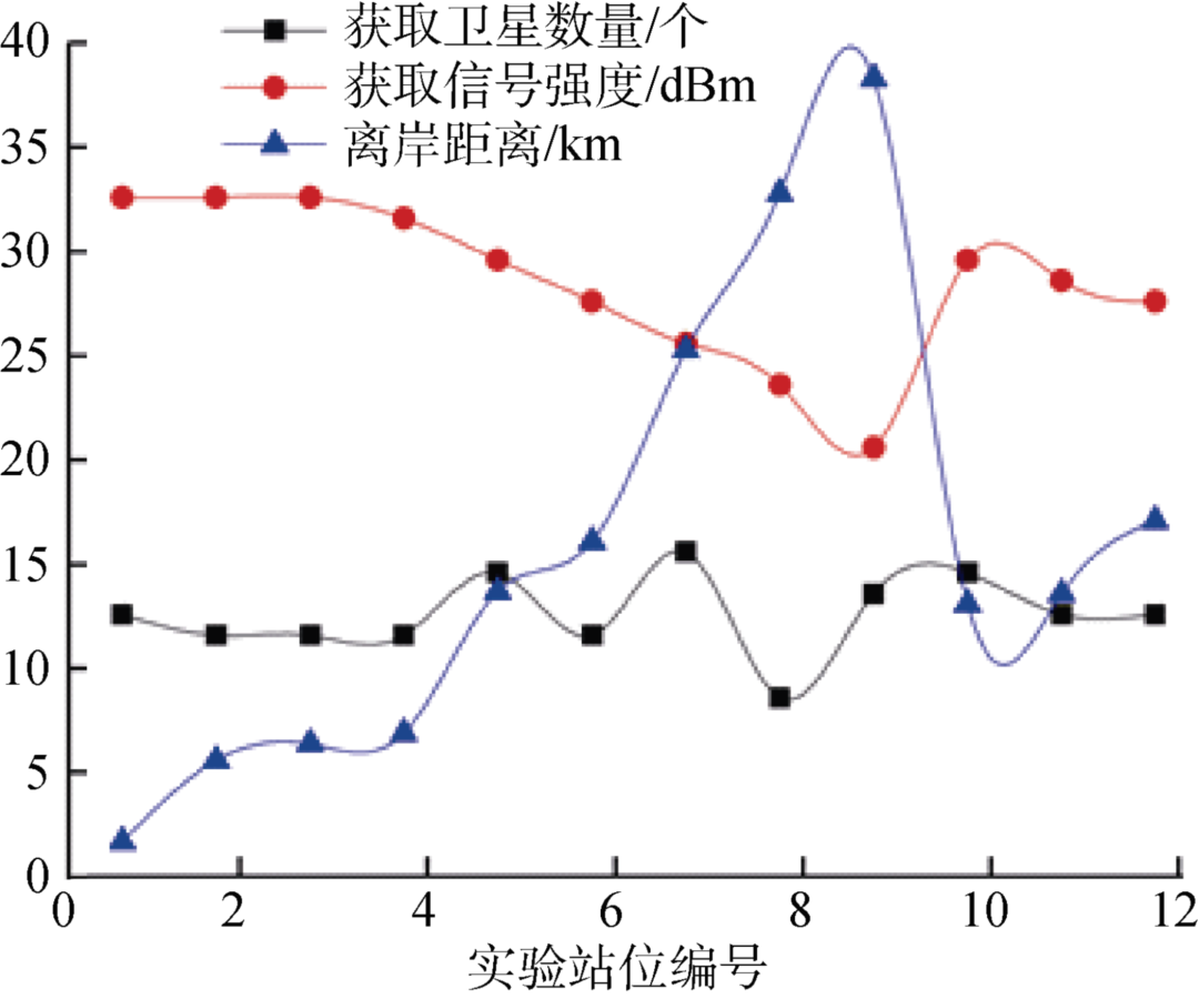
Figure 6 Relationship Between Number of Satellites, GSM Signal Strength, and Distance from Shore at Each Station


The low-power positioning beacon mentioned in this paper has shown stable operation in areas with network signal coverage after long-term testing, with a signal transmission duration of up to 60 days at a working interval of 15 seconds. However, due to the limitations imposed by mobile internet base stations, the beacon cannot function normally in offshore areas, especially in regions without mobile signals. Therefore, the applicable range of this product is clearly defined as within 20 nautical miles from the shore. Within this area, deploying underwater observation systems, this beacon serves as an auxiliary instrument, providing excellent cost performance. Additionally, due to its unique activation method via electrode open-circuit and short-circuit operations, it eliminates the need for pressure sensors and relays, reducing development costs, minimizing intermediate control links, simplifying hardware program design complexity, and lowering power consumption, optimizing performance compared to traditional beacons.
The beacon machine relies on electrodes to control its working state, and the materials for the electrodes must meet strict requirements due to long-term underwater operation. The types of materials previously attempted for the electrodes include 316L stainless steel and titanium. Stainless steel electrodes are cost-effective, but due to differences in raw materials and processing techniques, some manufacturers’ stainless steel electrodes have shown corrosion after several months of underwater operation; titanium electrodes are more expensive but stable in performance, showing no corrosion after long-term underwater operation. In actual development and application, electrodes made of these two materials have been designed for easy replacement, allowing users to choose the most suitable electrode material based on actual working requirements for targeted customization.
END
Source: Streams of Ocean Life; Article from “Marine Science” (2020, Issue 11); Authors: Jiang Jingbo et al.