M-Bus Master to CANopen— Gateway Converter-HD67051
Author: Zou Wuyi Mobile185-020-77899 Email: [email protected]
1 Product Features: HD67051-B2-xxx is a Gateway M-Bus to CANopen device. It has the following features:
- Provides electrical isolation between CANopen and M-Bus ;
- Baud rate and parity can be changed via software;
- Can be mounted on a DIN rail;
- Power supply range: 15…21V AC or 18…35V DC;
- Operating temperature range: -40°C to 70°C.
A maximum of 250 standard M-Bus devices can be connected to this gateway. The specific number of supported devices depends on the code represented by “xxx” in the model:
- HD67051-B2-20 supports up to 20 M-Bus devices;
- HD67051-B2-40 supports up to 40 M-Bus devices;
- HD67051-B2-80 supports up to 80 M-Bus devices;
- HD67051-B2-160 supports up to 160 M-Bus devices;
- HD67051-B2-250 supports up to 250 M-Bus devices.
For the HD67051-B2-160 model:
- The device must be installed horizontally on a 35mm DIN rail mounted on the wall or cabinet backplane.
- To avoid affecting airflow around the device, it is recommended not to obstruct the air circulation path.
For the HD67051-B2-250 model:
- The device must be installed horizontally on a 35mm DIN rail mounted on the wall or cabinet backplane.
- This model’s housing is equipped with a fan on the top. To avoid affecting airflow around the device, it is recommended not to obstruct the air circulation path and to ensure the fan is not blocked.
- It is recommended to install the device in a well-ventilated cabinet.
2 New Project / Open Project: The “New Project” button will create a folder containing the entire device configuration. Device configurations can also be imported or exported: To clone the configuration of the programmable M-Bus to CANopen gateway for configuring another device in the same way, the folder and all its contents must be retained; to clone a project for a different version of that project, simply copy the project folder to another name, and then open the new folder with the “Open Project” button; when creating a new project or opening an existing project, various parts of the software will be accessible:• “Set Communication”;• “M-Bus”;• “EDS File”;• “Update Device”;
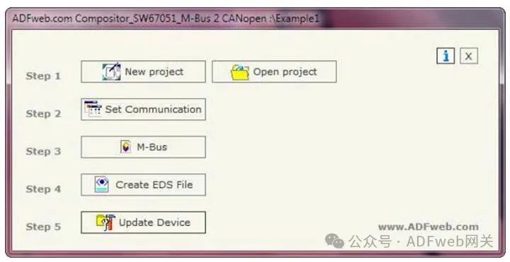
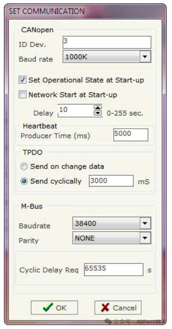
2 Set Communication:This section defines the basic communication parameters for the two buses (CANopen and M-Bus). The “Set Communication” button in the main window (Figure 2) can bring up the “SET COMMUNICATION” window (Figure 3). This window is divided into two parts, one for CANopen and the other for M-Bus.
CANopen field meanings are as follows:
- In the “ID Dev.” field, define the device ID for the CANopen end;
- In the “Baudrate” field, select the baud rate for the CANopen line;
- In the “Set Operational State at Start-Up” field, define the startup state for CANopen. That is: if this option is checked, the board will start in operational state; otherwise, it will start in pre-operational state;
- In the “Network Start at Start-Up” field, define the state of the CANopen network. That is: if this option is checked, the board will send a command to set all devices in the network to operational state;
- In the “Delay” field, define the delay time before sending CANopen network commands;
- In the “Producer Time (mS)” field, insert the delay time for sending network heartbeat. If the value of this field is zero, the gateway will only send a heartbeat once at startup; otherwise, it will send once every xx milliseconds;
- In the “TPDO” subsection, define the functionality of the transmission PDO. That is: if “Send on change data” is checked, the gateway will only send the PDO when data changes; otherwise, if “Send cyclically” is checked, the gateway will send the PDO at intervals defined in milliseconds.
M-Bus field meanings are as follows:
- In the “Baudrate” field, select the baud rate for the M-Bus line;
- In the “Parity” field, select the parity method for the line;
- In the “Cyclic Delay” field, insert the time (in seconds) between two scans.
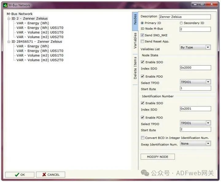
3 M-BUS: Through the main window’s “M-Bus” button (for SW67051, see Figure 2), you can open the “M-Bus Network” window (see Figure 4).
Node Section: In the “Node” section, you can create nodes for the M-Bus line. To create a new node, you need to select the address type to use (choose “MainID” or “SubID”), then issue a request and insert the M-Bus device’s “Main Address” (range: 1 to 250) or “Sub Address” (range: 0 to 99999999).
In the “Description” field, you can enter a short description of the node. If the “SendSND_NKE” field is checked, the gateway will send the “SND_NKE” frame to initiate communication. If the “Send Reset Application” field is checked, the gateway will send the “Application Reset” command to the slave device.
In the “Variable List” field, you can select the variable definition type to use. If you choose “By Type”, you need to fill in the correct values in all fields of the “Variable” section; if you choose “By Position”, you can insert the index of the required variable (more information can be found on page 13).
In the subsection “Node Status”, you can choose whether to save the status of the slave device’s node. You can use SDO and / or PDO. If using SDO, you must check the “EnableSDO” field and fill in the “SDO Index” field with the used SDO index. If using PDO, you must check the “EnablePDO” field… (original text incomplete).