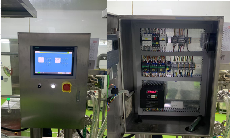
In the wave of industrial development, electrical control systems have always been the core force driving the improvement of production efficiency. From traditional button control to today’s PLC+HMI intelligent control, each technological iteration brings a qualitative leap. Today, let us step into the world of electrical transformation,exploring the secrets of upgrading button control to PLC+HMI control, unlocking a new future for industrial automation!Electrical transformation of equipment requires careful collection of various information, analyzing each aspect until fully understood.1 Hardware TransformationBefore Transformation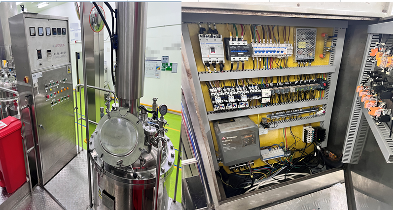 After Transformation
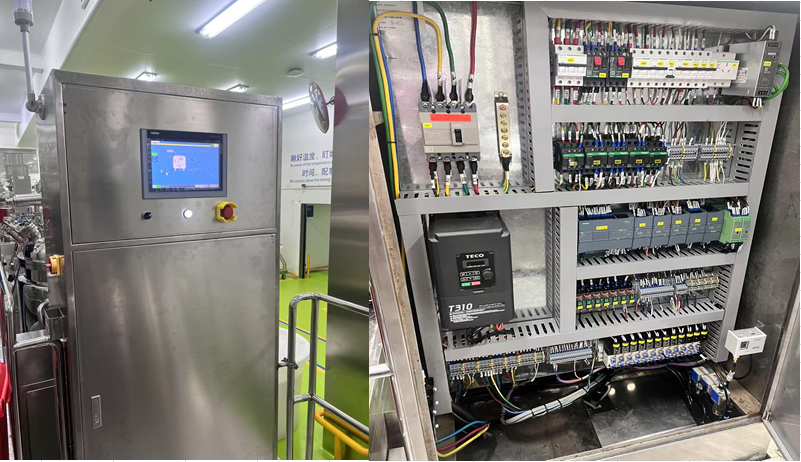
 2 Motor Types (Less Common)Multi-speed three-phase asynchronous motor
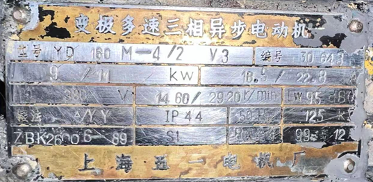 The stator winding of a three-phase dual-speed asynchronous motor has two connection methods:Δconnection and YY connection, as shown in the figure below.Wiring diagram of the stator winding of a three-phase dual-speed asynchronous motor
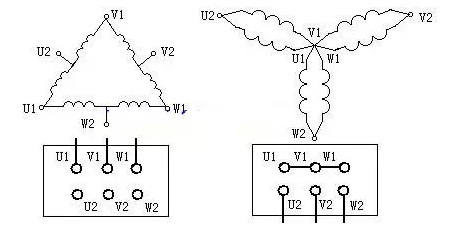 Wiring Diagram
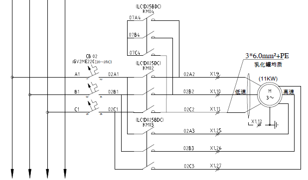 Deltaconnection for low-speed operation at 1460 RPM, contactor KM02 coil is powered for operation.Starconnection for low-speed operation at 1460 RPM, contactors KM03 and KM04 coils are powered for operation.Please note: KM02 and KM03 need to be interlocked; it is best to use 2 thermal relays for high and low speed.3. Frequency Converter (Less Common)3.1 TECO T310 Frequency Converter
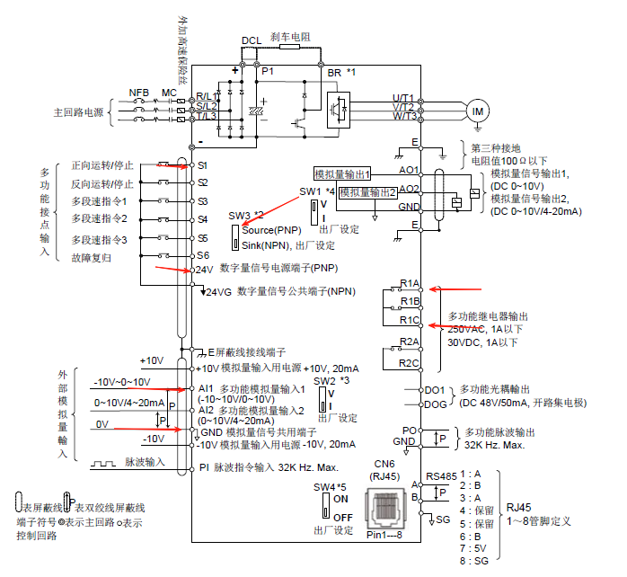 Using external terminal control:Start/Stop signal: S1, 24V. Use PNP signal, switch SW3 must be set to PNP.Speed setting: GND, AI1. 0~10V Please pay attention to the polarity.Fault: R1A, R1C.Specific Parameters:13-08 = 6 Restore factory settings
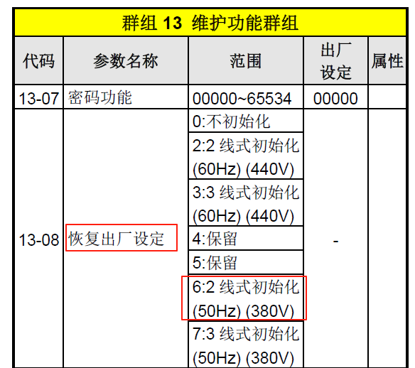 00-02 = 1 External terminal control
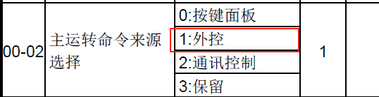 00-05 = 1 External (analog AI1)
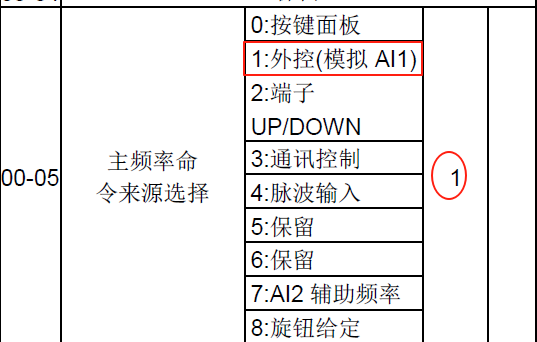 3.2 Panasonic VF200 Frequency Converter
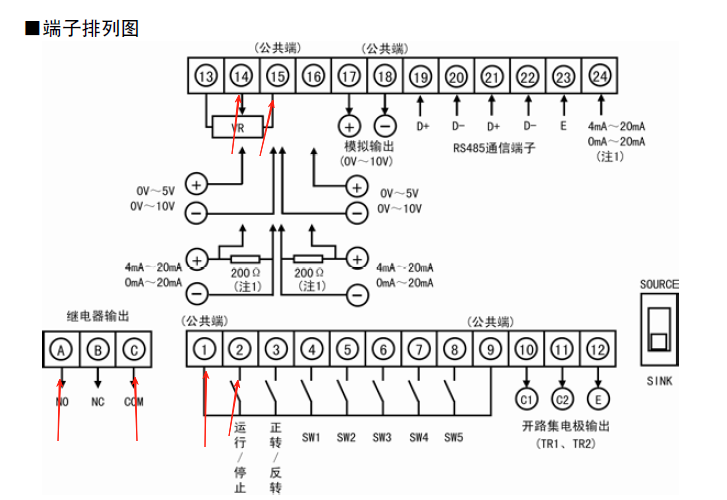 Using external terminal control:Start/Stop signal: 1, 2.Speed setting: 14+, 15-,Please pay attention to the polarity.Fault: A, C.Specific Parameters:P003 = 4 External control
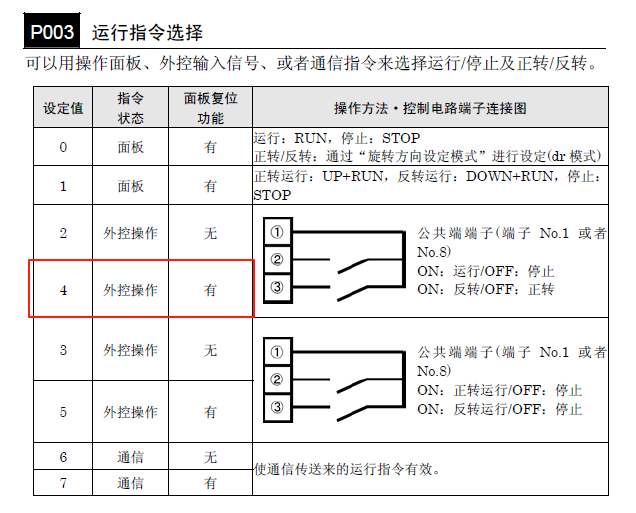 P004 = 4 External operation 0-10V
 P145 Action status of the motor, content displayed after running on the interface.Can display frequency, speed, current, etc.
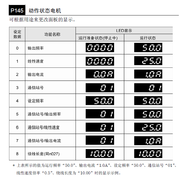 4. HMI Screen DisplayMain Screen
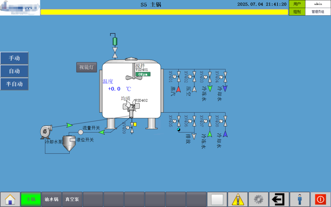 Motor Drive Panel
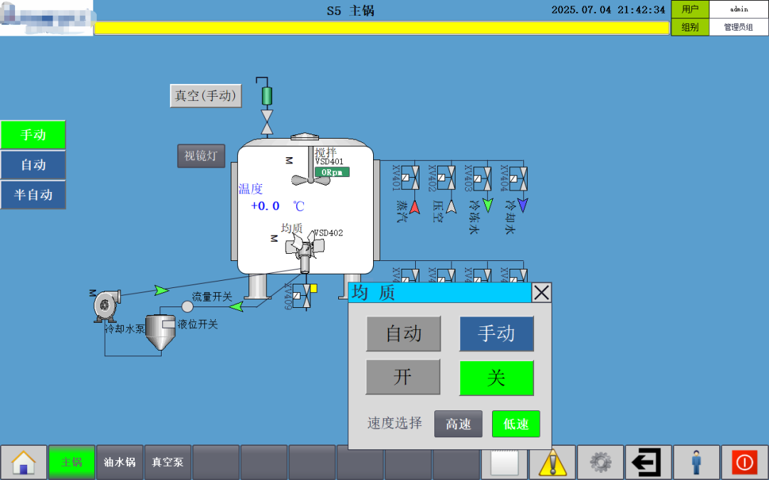 Valve Drive Panel
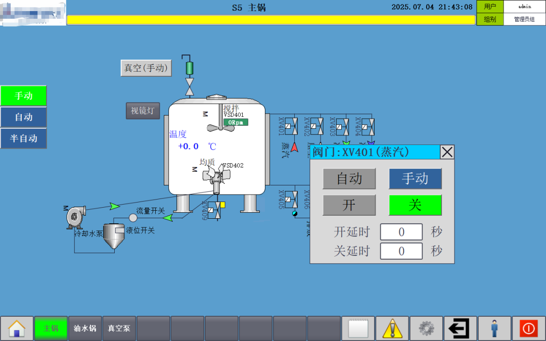 Automatic Recipe Interface
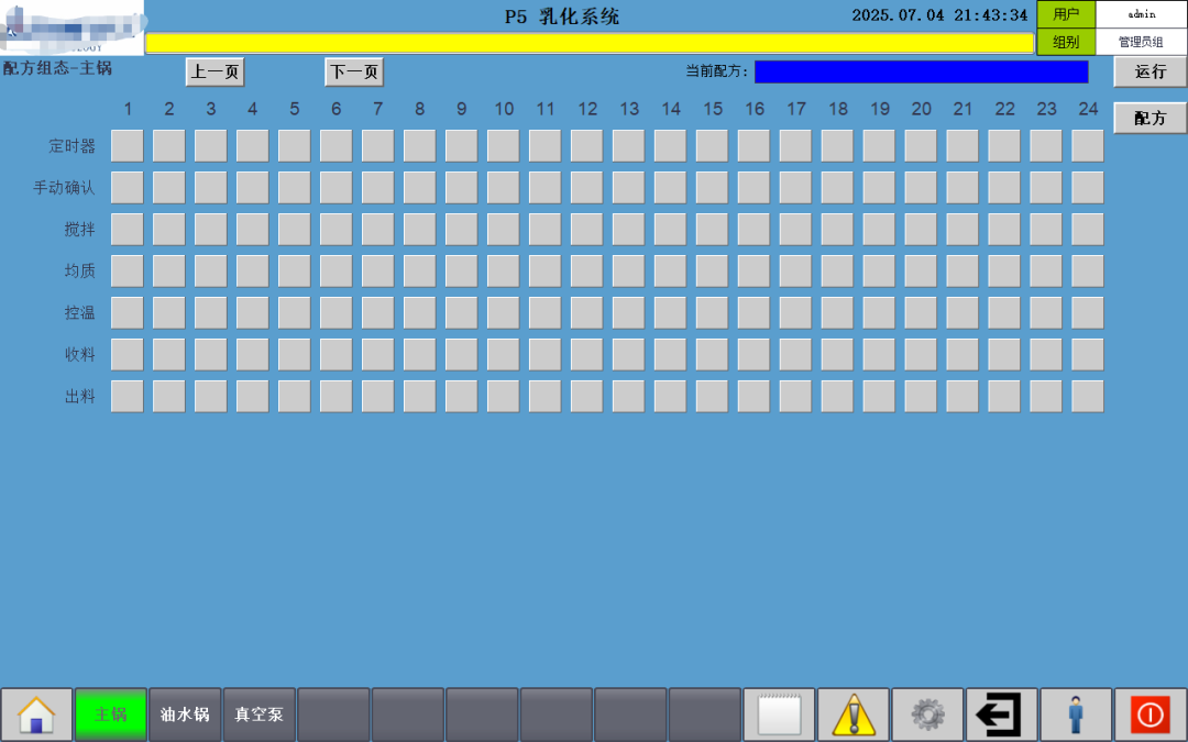 Automatic Recipe Program Running
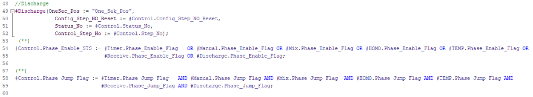
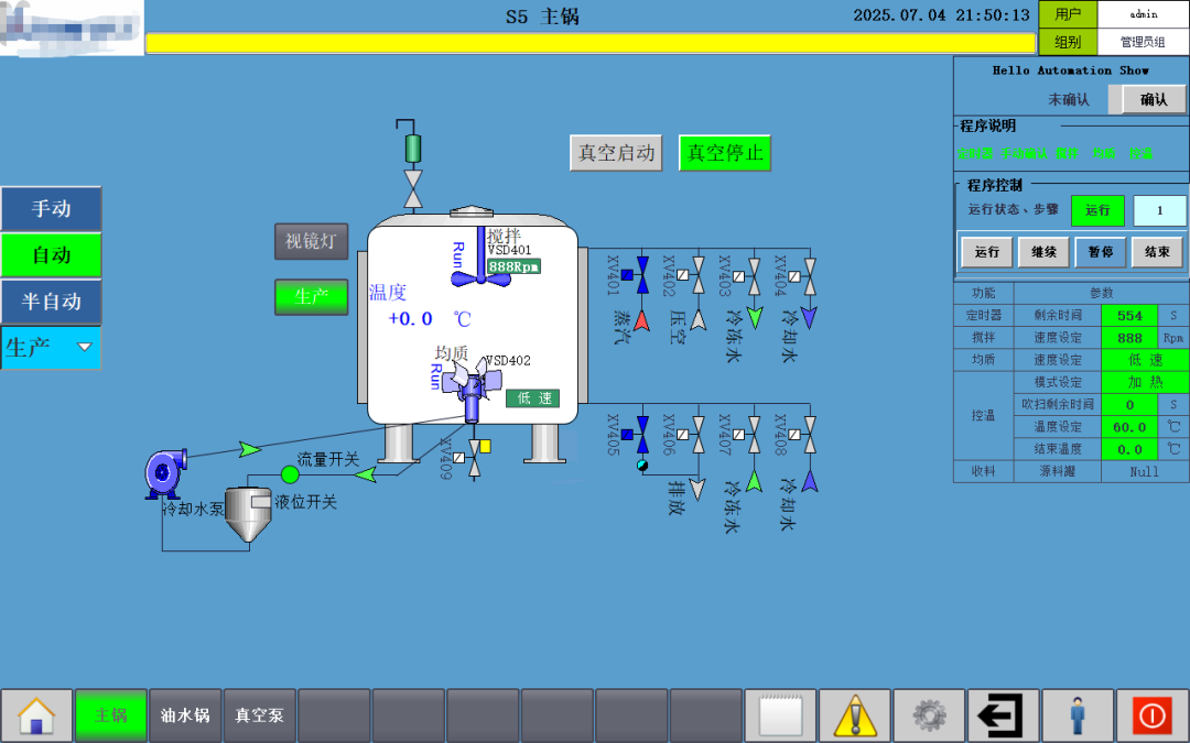 5. Code Display (Modular Programming))
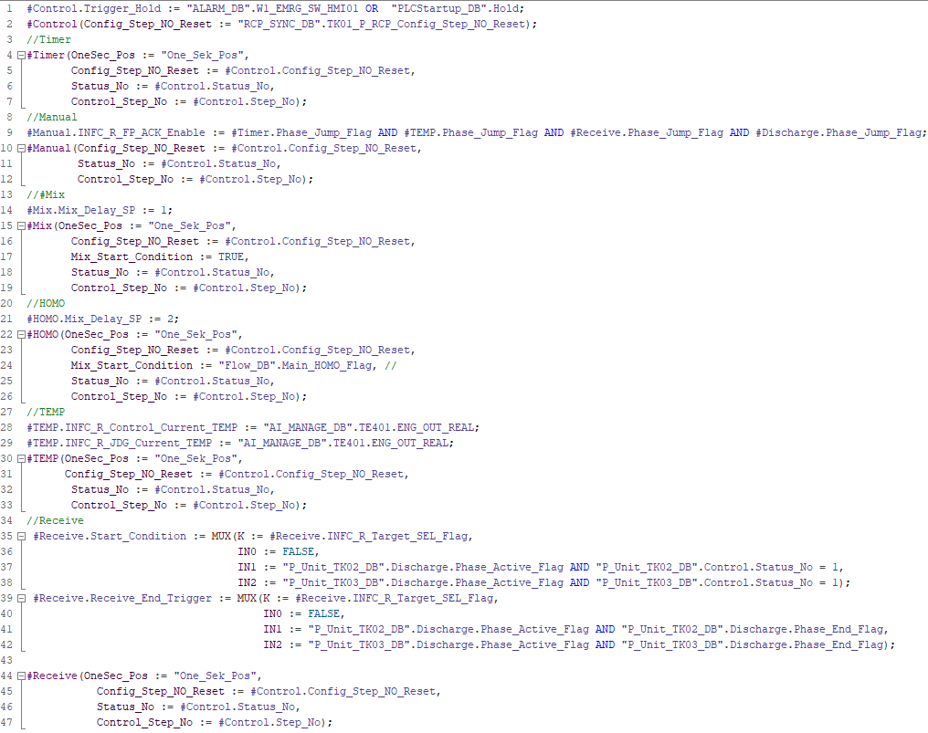
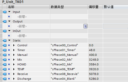
Alright, this concludes our explanation for this session. Feel free to leave comments and discuss in the comment section.
On WeChat, reply with the keyword “Electrical Transformation” in the chat interface to obtain materials(not involving programming parts!).Previous Reviews:
| Implementation and Display of Audit Operation Records Based on TIA Portal Comfort Touch Screen |
| Siemens PLC1200/1500 Dynamic Encryption Timing Collection Program: Efficiently Ensuring Project Payments |
| Solution for Missing Panel Image Prompt When Downloading TIA Portal WinCC (No Update Package Required) |
| Siemens S7-1200 and S7-200 CN Modbus RTU Communication |
| Dynamic Display of Secondary Confirmation Window Position for Siemens TP Series Panels |
| New Ways to Access Automation Show Content, Thank You for Being with Us! |