Follow Our Public Account to Not Miss Any Updates!!

This tutorial was originally published by the author strongerHuang in September 2018.
Tags: CAN, CANOpen, CanFestival
Copyright: Commercial Use Prohibited
Disclaimer:This document is for personal learning use only. Please contact the author for authorization before reprinting.
1Introduction
The previous article discussed CAN and CANOpen, and I believe everyone has a certain understanding of both. This article states that CAN is both a bus and a protocol. Therefore, we often hear about the CAN bus and the CAN protocol.
The CAN protocol and the CANOpen protocol are two different sets of protocols. From the perspective of software and hardware, the CAN protocol belongs to hardware protocols, while CANOpen belongs to software protocols.
This article will first provide an overview of the CAN network, giving everyone a global concept of the CAN bus protocol, and then delve into the underlying CAN bus protocol knowledge.
2
CAN Network
The CAN network can be understood as a network formed by multiple CAN devices connected on the same CAN bus, which we refer to as nodes. The topology of the CAN network is shown in the figure below:
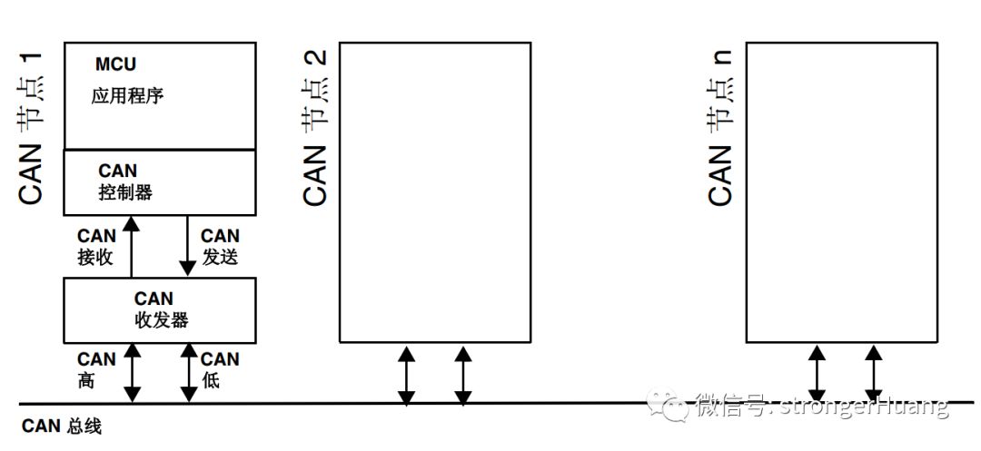
As shown in the figure, a CAN node mainly consists of three components: MCU application program, CAN controller, CAN transceiver.
2.1 MCU Application Program
I divide the MCU application program into three parts: business logic code, protocol layer code, and lower-level driver code.
A. Business Logic Code: This is determined by project requirements and is easy to understand. For example, I read data from a sensor and perform corresponding logical processing.
B. Protocol Layer Code: For example, the CANOpen that will be discussed later.
C. Lower-Level Driver Code: Configuring the corresponding parameters of the CAN bus and controlling the sending and receiving code.
2.2 CAN Controller
The internal structure of the CAN controller is quite complex, and generally, the CAN controller is integrated with the processor.
In fact, for programmers, it mainly consists of some control, status, configuration, and other registers.
For example, we see that some STM32 chips come with CAN, meaning the CAN controller is already integrated into the STM32 chip, and we just need to program the registers.
2.3 CAN Transceiver
CAN transceiver: Converts the TTL signals of the CAN transmission and reception pins (CAN_TX and CAN_RX) into the voltage signals of the CAN bus.
PS: You can think of CAN bus communication as UART communication via 485: the CAN controller is like the UART controller, while the CAN transceiver is like the 485 conversion chip.
3
ISO Standardized CAN Protocol
The main purpose of this chapter is to help everyone understand the layer at which the CAN bus resides in the OSI model.
3.1 ISO/OSI Basic Reference Model
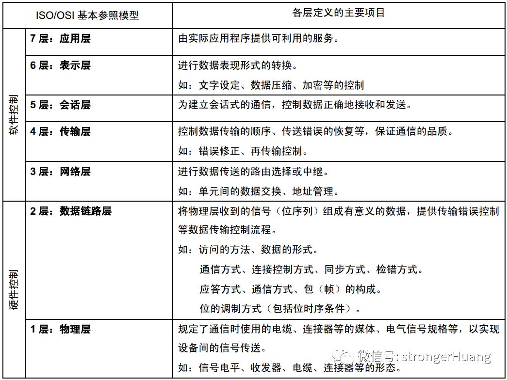
[Note]
ISO: International Standardization Organization;
OSI: Open Systems Interconnection;
3.2 Definition of CAN in the OSI Model
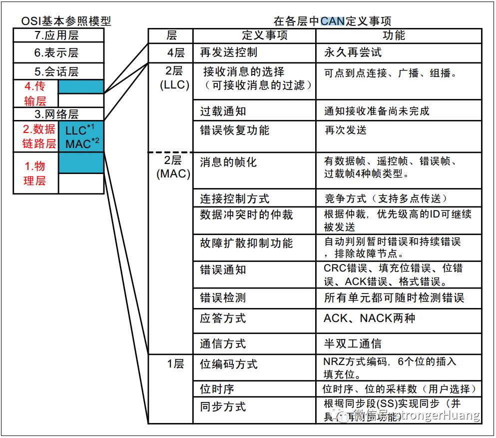
[Note]
LLC: Logical Link Control;
MAC: Medium Access Control;
From the above figure, we can see that the underlying hardware of the CAN bus (CAN controller, transceiver) mainly resides in the 1st and 2nd layers of the OSI model.
4
Overview of CAN Bus Protocol
The CAN bus protocol is a set of protocols established to ensure that communication (sending and receiving) data can be transmitted stably on the CAN bus.
There is a lot of content in the CAN bus protocol. To facilitate beginners’ understanding, this article will first briefly describe the CAN bus protocol, and subsequent articles will detail the content of the CAN bus protocol.
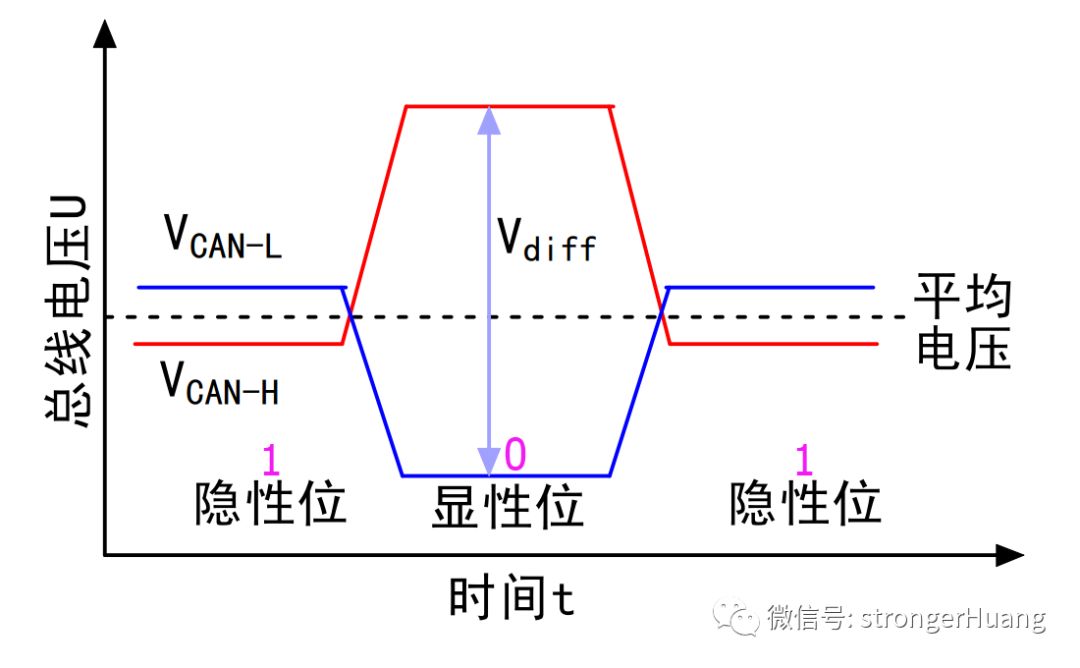
4.1 Bus Signal
The CAN bus uses a “two-wire” “differential” signal, where the invisible represents logic 1, and the visible represents logic 0. As shown in the figure below:
4.2 Priority
If at a certain moment, one device (node) sends 0 to the bus, and another device sends 1 to the bus, what will happen on the bus?
The answer: the bus will eventually show dominant, which means 0.
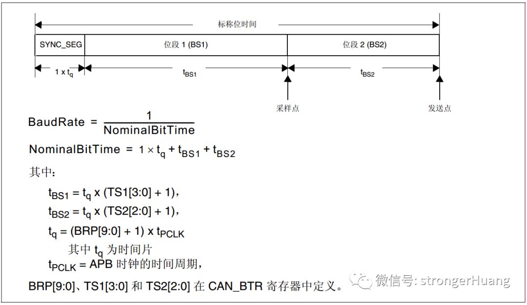
4.3 Bit Timing
Bit timing logic monitors the serial bus, performs sampling, and adjusts sampling points. During the adjustment of sampling points, synchronization needs to be performed at the start bit edge and subsequent edges.
In simple terms, it samples a bit in several segments, aiming to improve data transmission stability. In STM32, the lower-level driver code needs to perform bit timing programming, and you will also find the following bit timing diagram in the STM32 reference manual:
4.4 Types and Formats of Frames
There are various types of frames:
Data Frame: Used to send data from the transmitting unit to the receiving unit.
Remote Frame: Used by the receiving unit to request data from a transmitting unit with the same ID.
Error Frame: Used to notify other units of an error when one is detected.
Overload Frame: Used to inform the receiving unit that it is not yet ready to receive.
Frame Interval: Used to separate data frames and remote frames from the previous frame.
Data Frames and Remote Frames have both standard and extended formats. The standard format has an 11-bit identifier ID, while the extended format has a 29-bit ID.
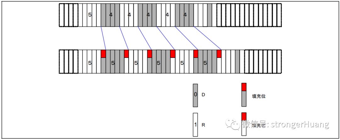
4.5 Bit Stuffing
Bit stuffing is a function set to prevent burst errors. When the same level persists for 5 bits, a bit of inverted data is added. As shown in the figure below:
4.6 Types of Errors
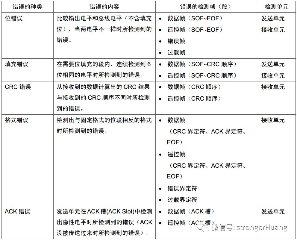
There is a lot of content in the CAN bus protocol. Beginners should first understand these points, and later articles will go into detail on each point, which will help everyone understand their meanings better.
5
Notes
1. Some text in this document comes from the internet and is for personal learning use only. Copyright reserved, commercial use prohibited.
2. This article was edited and organized by me alone, and there may be some errors.
3. This article is included in the public account 【strongerHuang】. Follow the public account and reply with 【CANOpen Series Tutorial】 to view the entire series of tutorials.
6Conclusion
If you find this article helpful, remember to like and share. (Likes are the motivation for the author to update articles)
Scan the QR code below to follow us and see more exciting content in the bottom menu!

Long press to recognize the QR code in the image to follow

Appreciation is recognition and support for the author!