If you still don’t understand NB-IoT after reading this article, come over and strangle me…
1
1G-2G-3G-4G-5G
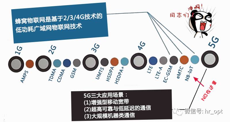
No explanation, just look at the picture. Where is NB-IoT?
2
NB-IoT Standardization Journey
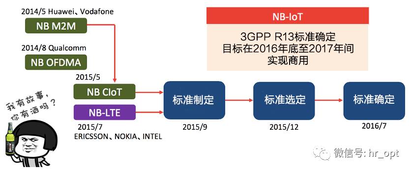
The standardization of 3GPP NB-IoT began in September 2015, and the R13 NB-IoT standard was completed in July 2016.
3
NB-IoT Design Goals and Use Cases
NB-IoT is primarily aimed at large-scale IoT connectivity applications, with the following design goals:
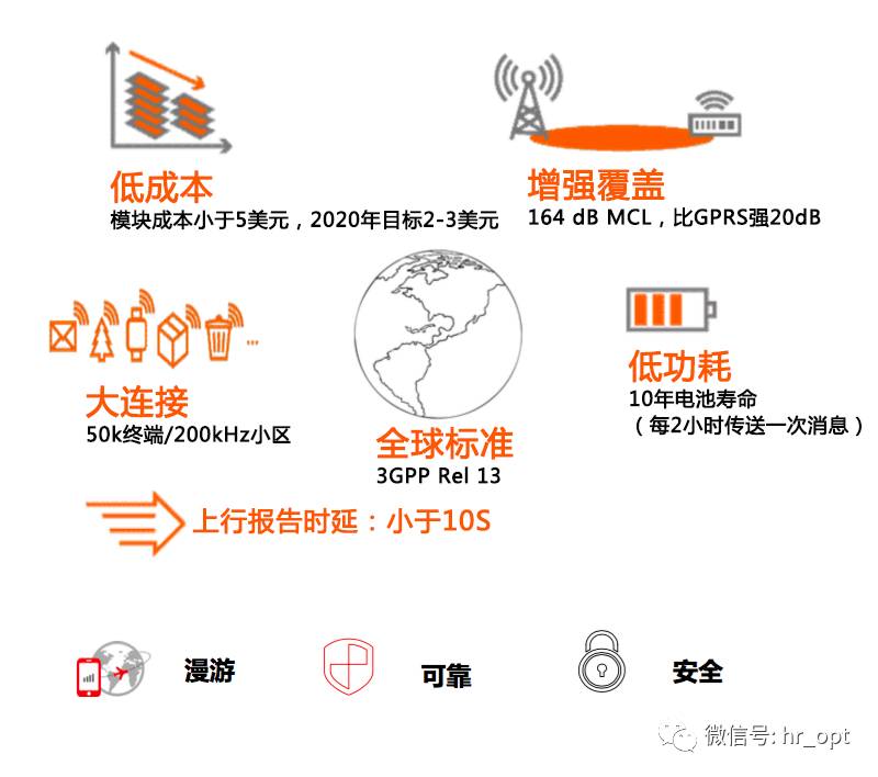
• Low cost, low complexity: Module cost is less than $5, with a target of $2-3 by 2020.
• Enhanced coverage: 164 dB MCL, 20 dB stronger than GPRS.
• Battery life: 10 years.
• Capacity: About 55,000 connected devices per cell.
• Uplink reporting latency: Less than 10 seconds.
4
Key Technologies of NB-IoT
How to enhance coverage?
What is coverage? It is the Maximum Coupling Loss (MCL), the path loss from the base station antenna port to the terminal antenna port.
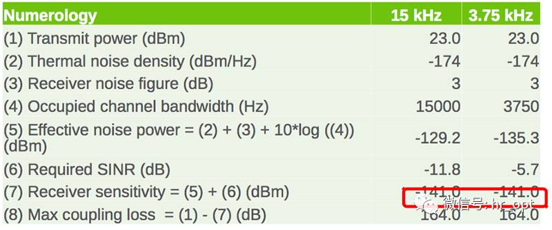
Simple definition:
Uplink MCL = uplink maximum transmit power – base station receive sensitivity.
Downlink MCL = downlink maximum transmit power – terminal receive sensitivity.
NB-IoT’s MCL is 164 dB.
① Increase uplink power spectral density
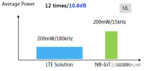
Uplink control information and service information are sent in a narrower LTE bandwidth, resulting in a greater PSD (Power Spectrum Density) gain under the same transmit power, reducing the demodulation requirements for the receiver.
NB-IoT uplink power spectral density is enhanced by 17 dB. Considering that the maximum transmit power of GSM terminals can reach 33 dBm, while NB-IoT’s maximum transmit power is 23 dBm, the actual NB-IoT terminal has a power spectral density 7 dB higher than that of GSM terminals.
② Retransmission
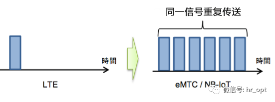
Retransmission means sending a transmission block over multiple subframes. Repetition Gain = 10 log Repetition Times, meaning that retransmitting twice can increase the gain by 3 dB. NB-IoT can support up to 2048 retransmissions downlink and 128 retransmissions uplink.
Note: The receiver does not require decoding processing gain (approximately 3-4 dB).
How to reduce costs?
① Reduce protocol stack processing overhead
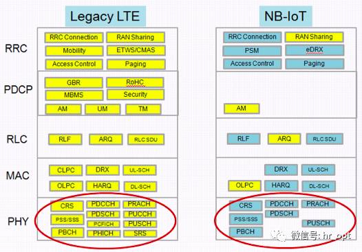
As shown in the above figure, NB-IoT eliminates the LTE physical layer’s uplink shared channel (PUCCH), physical hybrid automatic repeat request indicator channel (PHICH), etc.
② Reduce unnecessary hardware
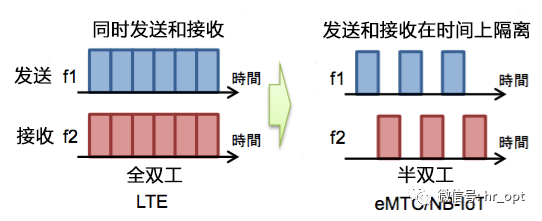
Single antenna and FDD half-duplex mode reduce RF costs.
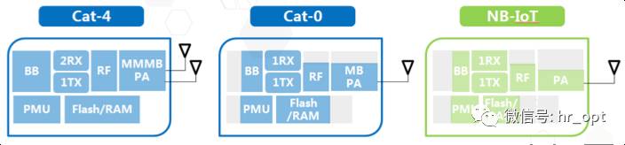
Release 13 NB-IoT supports only FDD half-duplex mode, which means it does not need to handle sending and receiving simultaneously, making it cheaper and more power-efficient than full-duplex.
Note: Low data rates and low bandwidth inherently mean a reduction in chip processing complexity.
How to save power?
① PSM (Power Saving Mode)
What is the best way to save power? Of course, turning off is the most power-saving.
Mobile phones need to be on standby at all times; otherwise, what if someone calls you and you can’t be reached? But this means the phone needs to listen to the network from time to time, which consumes power.
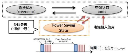
However, IoT terminals are different from mobile phones; they spend most of their time sleeping, sending only one or two messages a day or even a week, and then going back to sleep. Therefore, they do not need to listen to the network at all times. PSM allows IoT terminals to send data and then enter a sleep state, similar to turning off, without any communication activities.
② eDRX
DRX (Discontinuous Reception) means not continuously receiving. eDRX is extended discontinuous reception.
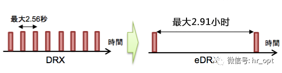
Mobile phones can receive signals intermittently to save power. NB-IoT extends this discontinuous interval to 2.91 hours, further saving power.
Additionally, NB-IoT only supports cell reselection and does not support handover, which reduces measurement overhead; simplifying air interface signaling reduces single transmission power consumption.
5
What are the differences between NB-IoT and LTE?
First, let’s briefly recall LTE…

Wireless frame length is 10ms, subframe is 1ms, time slot is 0.5ms, with 10 subframes per wireless frame, and each subframe contains 2 time slots, using Orthogonal Frequency Division Multiple Access (OFDMA) technology for downlink, with a subcarrier spacing of 15kHz… such a familiar sight.

NB-IoT is similar. NB-IoT is a modified version of FDD LTE technology, including frame structure, downlink OFDMA, uplink SC-FDMA, channel coding, interleaving, etc., most of which are inherited from LTE technology, which can be understood as a simplified version of FDD LTE technology.
This is the main reason why NB-IoT is said to be the fastest communication standard completed in history (completed in just over six months). Another benefit is its compatibility with existing LTE, reducing the investment in NB-IoT devices and software, allowing quick capture of the IoT windfall.
However, there are also differences. The following sections will introduce NB-IoT while comparing it with LTE.
5.1 Transmission Schemes
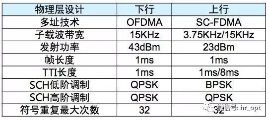
Downlink Transmission Scheme
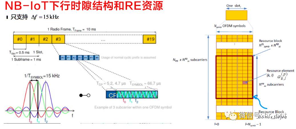
NB-IoT downlink is consistent with LTE, using Orthogonal Frequency Division Multiple Access (OFDMA) technology, with a subcarrier spacing of 15 kHz, time slot, subframe, and wireless frame lengths of 0.5 ms, 1 ms, and 10 ms respectively, including the number of OFDM symbols per time slot and cyclic prefix being the same as LTE.
NB-IoT has a carrier bandwidth of 180 kHz, equivalent to the bandwidth of one LTE PRB (Physical Resource Block), i.e., 12 subcarriers * 15 kHz/subcarrier = 180 kHz, ensuring downlink compatibility with LTE. For example, when deploying within LTE carrier bandwidth, the downlink NB-IoT PRB can maintain orthogonality with other LTE PRBs.
Uplink Transmission Scheme
NB-IoT uplink supports multi-tone transmission and single-tone transmission.
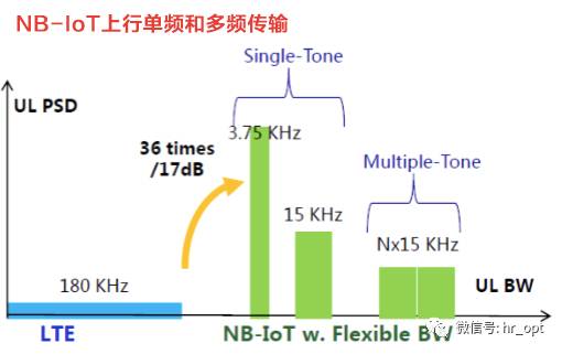
Multi-tone transmission is based on SC-FDMA, with a subcarrier spacing of 15 kHz, 0.5 ms time slot, and 1 ms subframe (same as LTE). Single-tone transmission can have a subcarrier spacing of 15 kHz and 3.75 kHz, where 15 kHz is the same as LTE to maintain compatibility in uplink; when the subcarrier is 3.75 kHz, one time slot in its frame structure is 2 ms long (containing 7 symbols), 15 kHz is an integer multiple of 3.75 kHz, so it has minimal interference with LTE systems.
Like the downlink, the total system bandwidth for NB-IoT uplink is 180 kHz.
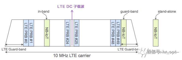
5.2 Deployment Methods
As we know, NB-IoT can be deployed in three ways: Standalone, Guard band, and In-band. Standalone deployment is suitable for re-farming GSM frequency bands, where the GSM channel bandwidth is 200 kHz, which just leaves space for NB-IoT’s 180 kHz bandwidth, with a 10 kHz guard interval on both sides. Guard band deployment utilizes unused 180 kHz resource blocks in the LTE edge guard band. In-band deployment utilizes any resource block in the middle of the LTE carrier.
However, the last sentence of the previous paragraph is incorrect. In the in-band deployment mode, some PRBs cannot be occupied by NB-IoT.
Like LTE, when an NB-IoT terminal powers on and searches for a carrier (cell), it will repeat the search and detection process for PSS/SSS in the possible frequency range until it finds the corresponding carrier (NB-IoT anchor carrier), with a frequency scan raster size of 100 kHz.
The so-called raster is also the minimum unit used to adjust the frequency position of LTE carriers, indicating that the interval between frequency points should be an integer multiple of 100 kHz, equivalent to dividing a highway into several lanes, with the center distance between two lanes being an integer multiple of 100 kHz. The mobile terminal scans the frequency in integer multiples of 100 kHz.
This 100 kHz frequency scan raster means that in in-band deployment, the NB-IoT anchor carrier must be located in a specified PRB. For example, for a 10 MHz LTE bandwidth, NB-IOT cannot occupy the PRBs where the synchronization and broadcast channels are located, and must also meet the 100 kHz raster requirement, so its in-band NB-IoT can only be located in PRBs 4, 9, 14, 19, 30, 35, 40, and 45.
Additionally, a 2.5 kHz offset must be applied. (This is really quite troublesome)
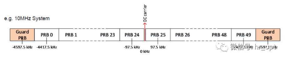
As shown in the above figure, taking NB-IoT’s in-band deployment in a 10 MHz LTE bandwidth as an example, the PRB to the right of the DC subcarrier is #25, with a center frequency of 97.5 kHz (equivalent to 6 subcarriers), which deviates by 2.5 kHz from the nearest 100 kHz raster.
Since the center frequency interval of the two adjacent PRBs above the DC subcarrier is 180 kHz, the center frequencies of PRBs #30, #35, #40, and #45 are all 2.5 kHz away from the nearest 100 kHz raster. (As long as a 2.5 kHz offset is applied, the 100 kHz raster requirement can be satisfied).
Next, looking at the above figure, for 10 MHz and 20 MHz LTE carriers, some PRBs meet the condition of being 2.5 kHz away from the nearest 100 kHz raster. However, for 3 MHz, 5 MHz, and 15 MHz LTE carrier bandwidths, these PRBs deviate from the nearest 100 kHz raster by at least 7.5 kHz.
So, here is a homework question: What to do in the case of Unicom’s 900 MHz band with only 6 MHz bandwidth?
Similar to the in-band deployment mode, in the guard band deployment mode, the NB-IoT anchor carrier must also meet the requirement that its center frequency does not exceed a 7.5 kHz deviation from the nearest 100 kHz raster because the terminal needs to meet the raster deviation requirement of less than 7.5 kHz when searching for the cell to complete network synchronization.
NB-IoT supports multi-carrier configuration, and its carriers can be divided into two categories: Anchor Carrier and Non-Anchor Carrier. For non-anchor carriers, the 100 kHz raster deviation requirement does not need to be met.
However, some PRBs (e.g., #25) also meet the condition of being 2.5 kHz away from the nearest 100 kHz raster; why can’t the PRBs for in-band NB-IoT deployment be used?
The answer is that NB-IoT cannot use the 6 PRBs in the middle of the LTE carrier, which must be used for LTE synchronization and broadcast channels.
5.3 Physical Channels
The design of NB-IoT physical channels is largely based on LTE; this article mainly introduces the differences between the two.
1) Downlink
For the downlink, NB-IoT defines three physical channels:
① NPBCH, Narrowband Physical Broadcast Channel
② NPDCCH, Narrowband Physical Downlink Control Channel
③ NPDSCH, Narrowband Physical Downlink Shared Channel
It also defines two physical signals:
① NRS, Narrowband Reference Signal
② NPSS and NSSS, Primary Synchronization Signal and Secondary Synchronization Signal
Unlike LTE, since NB-IoT has a maximum frequency bandwidth of only one PRB, these downlink physical channels use time division multiplexing mode, meaning they appear alternately at different times.
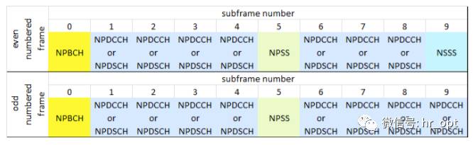
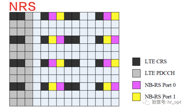
▲ Time Division Multiplexing between NB-IoT Downlink Physical Channels and Signals
As shown in the above figure, NB-IoT subframes are allocated to different physical channels and signals. Each NB-IoT subframe occupies one PRB (12 subcarriers) in the frequency domain and lasts for 1 ms in the time domain.
NPSS and NSSS
NPSS and NSSS are used by NB-IoT terminals to perform cell search, including time and frequency synchronization and Cell ID detection. Because the synchronization sequence of LTE occupies 6 PRBs, NB-IoT cannot occupy these 6 PRBs. To avoid conflicts, NB-IoT needs to be redesigned.
NPSS is located in subframe #5 of each 10 ms wireless frame, with a period of 10 ms, using the last 11 OFDM symbols in each subframe (as shown in the figure below).
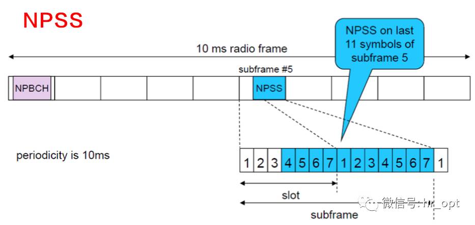
For NB-IoT terminals, executing NPSS detection is a computationally complex process, which contradicts its design goal of simplification; therefore, NPSS is designed as a short ZC (Zadoff-Chu) sequence.
NSSS is located in subframe #9, with a period of 20 ms, appearing only in even frames, also using the last 11 OFDM symbols in each subframe.
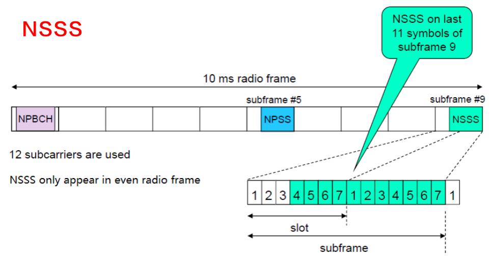
NPSS provides time and frequency synchronization reference signals for NB-IoT terminals. Unlike LTE, NPSS does not carry any cell information, while NSSS carries PCI.
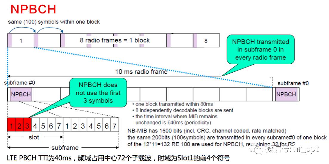
NPBCH
NPBCH is located in subframe #0 of each wireless frame, with a TTI of 640 ms, carrying MIB-NB (Narrowband Master Information Block), while other system information such as SIB1-NB is carried on NPDSCH.
NPDCCH and NPDSCH
NPDCCH carries scheduling information for uplink and downlink data channels, including HARQ acknowledgment information for uplink data channels, paging indications, and random access response scheduling information, as well as data information from higher layers, paging messages, system messages, and random access response messages.
As shown in the NB-IoT physical channel time division multiplexing diagram above, many subframes are allocated to NPDCCH and NPDSCH.
To reduce terminal complexity, all downlink channels use LTE’s TBCC code. Additionally, the maximum transmission block size (TBS) for NPDSCH is 680 bits, while LTE supports a maximum TBS of over 70,000 bits without spatial multiplexing.
NRS
NRS (Narrowband Reference Signal), also known as pilot signal, mainly serves to estimate downlink channel quality for coherent detection and demodulation by the terminal. NRS is transmitted in all downlink subframes, regardless of whether data is being sent.

NRS is time-frequency multiplexed with the information-bearing symbols of subframes carrying NPBCH, NPDCCH, and NPDSCH, using 8 REs per subframe for each antenna port.
Uplink
For the uplink, NB-IoT defines two physical channels:
① NPUSCH, Narrowband Physical Uplink Shared Channel.
② NPRACH, Narrowband Physical Random Access Channel.
Additionally, there is DMRS, uplink demodulation reference signal.
NPRACH
Since the bandwidth of LTE’s PRACH channel is 1.08 MHz, which is far greater than NB-IoT’s uplink bandwidth, it needs to be redesigned.
Unlike LTE’s Random Access Preamble using ZC sequences, NB-IoT’s Random Access Preamble uses single-tone transmission (3.75 kHz subcarrier), and the symbols used are of a fixed value. A single Random Access Preamble transmission consists of four Symbol Groups, with each Symbol Group containing five symbols plus a CP (as shown in the figure below).
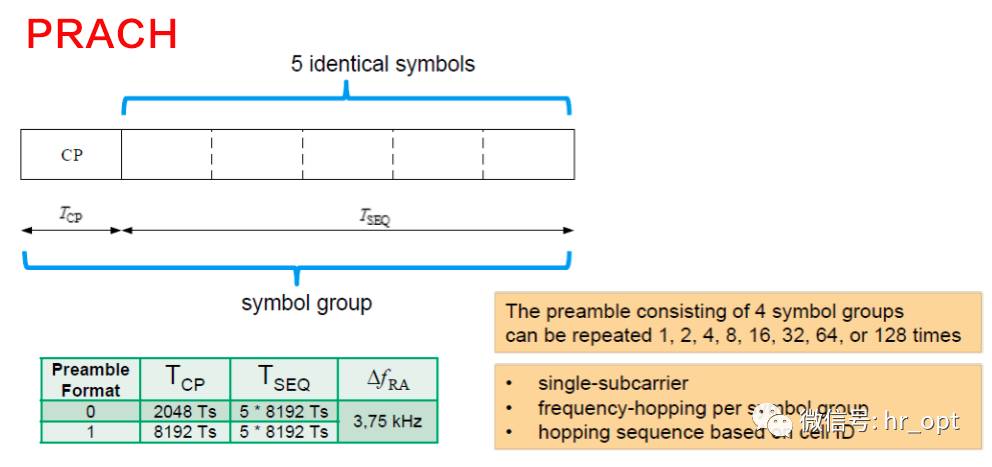
A NPRACH preamble consists of four Symbol Groups. Each Symbol Group will have frequency hopping. The selected Random Access Preamble is the one that starts with a specific subcarrier.

▲ NPRACH Frequency Hopping
When the CP length is 66.67 μs (Format 0), the cell coverage radius reaches 10 km. When the CP length is 266.7 μs (Format 1), the coverage radius reaches 40 km. To extend coverage, the NPRACH preamble can be repeated up to 128 times.
NPUSCH
NPUSCH is used to transmit uplink data and uplink control information, with single-tone or multi-tone transmission (as previously described).
NPUSCH defines two formats: Format 1 and Format 2.
Format 1 is designed for uplink channel data on UL-SCH, using the same Turbo code error correction as LTE, with a resource block size much lower than LTE, not exceeding 1000 bits.
Format 2 is used for HARQ acknowledgment signaling on NPDSCH, transmitting uplink control information (UCI), using repetition codes for error correction.
The minimum unit of transmission block mapping is called a resource unit (RU), which is determined by NPUSCH format and subcarrier spacing.
Unlike LTE systems where the basic unit of resource allocation is a subframe, NB-IoT uses the number of subcarriers and time slots as the basic unit of resource allocation, as shown in the table below:
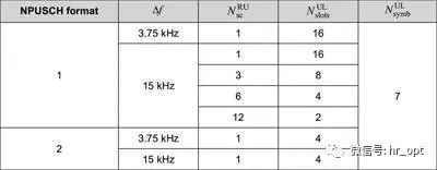
For NPUSCH format 1, when the subcarrier spacing is 3.75 kHz, only single-tone transmission is supported, with one RU in the frequency domain containing 1 subcarrier and in the time domain containing 16 time slots, so the length of one RU is 32 ms.
When the subcarrier spacing is 15 kHz, both single-tone and multi-tone transmissions are supported, with one RU containing 1 subcarrier and 16 time slots, with a length of 8 ms; when one RU contains 12 subcarriers, it has a time length of 2 time slots, i.e., 1 ms, which is exactly one subframe in the LTE system. The time length of the resource unit is designed to be a power of 2 to use the resource more effectively and avoid resource gaps that lead to waste.
For NPUSCH format 2, RU is always composed of 1 subcarrier and 4 time slots, so when the subcarrier spacing is 3.75 kHz, one RU lasts 8 ms; when the subcarrier spacing is 15 kHz, one RU lasts 2 ms.
NPUSCH format 2 modulation method is BPSK.
NPUSCH format 1 modulation method varies in the following two situations:
● For RUs containing one subcarrier, BPSK and QPSK are used.
● In other cases, QPSK is used.
This part is a bit convoluted; to understand it differently:
① NPUSCH supports single-tone transmission at 15 kHz or 3.75 kHz. To reduce the Peak-to-Average Power Ratio (PAPR), single-tone transmission uses π/2 BPSK or π/4 QPSK.
② If NPUSCH supports multi-tone transmission, QPSK is used.
(Supplement: NB-IoT downlink modulation uses QPSK, downlink channel coding uses TBCC, and uplink channel coding uses Turbo codes)
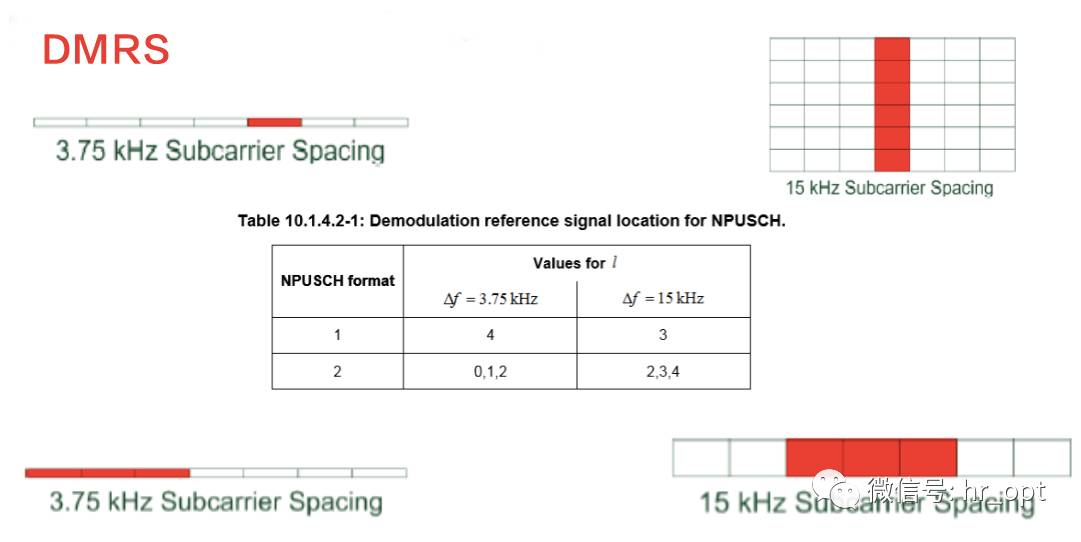
DMRS
DMRS is used for channel estimation. NPUSCH Format 1 structure is the same as LTE PUSCH time slot structure, with each time slot containing 7 OFDM symbols, with one symbol in the middle as DMRS. Format 2 structure also has 7 OFDM symbols per time slot, but uses the middle 3 symbols as DMRS.
5.4 Resource Mapping
In this section, we will describe how NB-IoT resource mapping is deployed in LTE carriers to ensure optimal coexistence performance with LTE. Essentially, this is done by avoiding mapping NB-IoT signals to resource elements already used by traditional LTE signals to maintain orthogonality between the two.
To ensure coexistence with LTE systems, NB-IoT signals must avoid mapping to REs (Resource Elements, the smallest resource unit in LTE physical resources) already used by LTE to maintain orthogonality between the two.
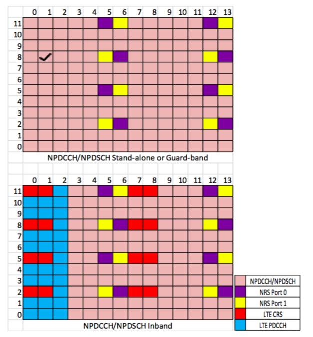
As shown in the above figure, each column represents an RE in an OFDM symbol, with each OFDM symbol containing 12 REs (corresponding to 12 subcarriers).
For standalone and guard band deployment modes, there is no need to protect LTE resources. Therefore, NPDCCH, NPDSCH, and NRS can utilize all resources in the PRB.
For in-band deployment mode, NPDCCH, NPDSCH, and NRS cannot be mapped to REs occupied by LTE CRS and PDCCH.
NB-IoT terminals determine the deployment mode (in-band/guard band/standalone) and CI through cell search, and then identify which REs are used by LTE, allowing the terminal to map NPDCCH and NPDSCH symbols to available REs. NPSS, NSSS, and NPBCH do not know the deployment mode during initial synchronization and acquisition of the main system information; therefore, NPSS, NSSS, and NPBCH avoid using the first three OFDM symbols of each subframe, as these resources may be used by LTE PDCCH.
5.5 Synchronization
Synchronization is an important part of cellular communication systems. When a terminal is powered on for the first time, it needs to detect a “suitable cell” to reside in, and then obtain symbol, subframe, frame timing, and carrier frequency synchronization. For frequency synchronization, the terminal needs to obtain synchronization information from the base station to calibrate, correcting frequency deviations caused by inaccurate local oscillators. Additionally, since there are multiple cells, the terminal needs to identify its designated cell based on NB-PCID.
Thus, the entire synchronization process actually includes time synchronization calibration, frequency offset correction, and acquisition of CI and subframe and frame number references.
NB-IoT’s characteristics include low cost and strong coverage. Low cost means that NB-IoT terminals are configured with low-cost oscillators, with initial carrier frequency offsets as high as 20 ppm. Coupled with the previously mentioned 2.5 kHz or 7.5 kHz raster offsets introduced in in-band and guard band deployment modes, this further increases carrier frequency offsets. Another characteristic of NB-IoT—enhanced coverage—means that many terminals are located in very low SNR network environments, such as basements.
How can precise synchronization be achieved under carrier frequency offsets and low SNR environments? Although the synchronization process of NB-IoT is similar to LTE, NB-IoT has modified the synchronization sequence to address the above two issues.
As mentioned earlier, NPSS and NSSS are used for synchronization. NPSS occupies subframe #5 of each frame, while NSSS occupies subframe #9 of each even frame. NPSS is used to obtain symbol timing and carrier frequency offset, while NSSS is used to acquire NB-PCID, lasting for an 80 ms block. For terminals in ultra-low SNR environments, detecting in a single 10 ms period is insufficient; an accumulation process over multiple 10 ms is required. NPSS is designed based on this time accumulation to exchange time for accuracy, using a weighted accumulation process to correct frequency offsets. The worse the coverage signal, the higher the number of accumulations required.
After NPSS and NSSS synchronization is completed, the terminal obtains information such as symbol timing, carrier frequency offset, and NB-PCID. Then, the terminal acquires MIB information broadcasted through the NPBCH channel located in subframe #0 of each frame. NPBCH consists of eight self-decoding sub-blocks, each repeated eight times, occupying subframe #0 of eight consecutive frames. This design is intended to allow terminals in deep coverage to successfully acquire information.
Through the above design, NB-IoT effectively compensates for carrier frequency offsets and completes NPSS and NSSS synchronization and MIB information acquisition. As for raster offsets, especially the 7.5 kHz offset, it is somewhat difficult to solve.
A 7.5 kHz raster offset can cause a timing drift of 5.33 seconds (assuming a carrier frequency of 900 MHz), which exceeds the duration of the cyclic prefix and can disrupt the orthogonality of the OFDM downlink. The only solution is to sacrifice cost and increase computational complexity to improve detection performance.
Therefore, this resolves the homework question: “What to do in the case of Unicom’s 900 MHz band with only 6 MHz bandwidth?”.
As for smaller raster offsets, since there is only one NPBCH subframe in every ten subframes, it is achievable.
5.6 Random Access
When a wireless link and scheduling request need to be established, NB-IoT performs random access. One of the main purposes of random access is to achieve uplink synchronization to maintain uplink orthogonality.
Similar to LTE, NB-IoT’s contention-based random access includes four steps:
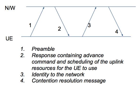
(1) UE sends a random access preamble
(2) The network sends a random access response (containing TA command and uplink resource scheduling to be used in step three)
(3) UE uses the scheduled resources and responds to the network with its identity
(4) The network sends a message to resolve the multi-UE contention access issue.
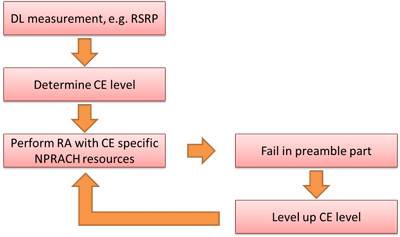
To meet different coverage levels, the system can configure up to three NPRACH resource configurations within a cell, each configuration specifies the repetition value of the random access preamble. The terminal estimates the coverage level (CE Level) based on the measured downlink signal strength and uses the NPRACH resources configured according to the coverage level to send the random access preamble.
NB-IoT allows flexible configuration of NPRACH resources in time and frequency:
Time domain: Periodicity of NPRACH resources, start time of NPRACH resources.
Frequency domain: Frequency position (based on subcarrier offset) and number of subcarriers.
In summary, the terminal determines the CE Level by measuring downlink signal strength and sends the random access preamble using the NPRACH resources specified by that CE Level. Once the random access preamble transmission fails, the NB-IoT terminal will retry with an upgraded CE Level until all CE Level’s NPRACH resources have been attempted (as shown in the figure below).
The random access process of NB-IoT is very similar to that of LTE and will not be elaborated further.
5.7 Scheduling and HARQ
Due to limited resources and support for repeated transmissions, if uplink uses synchronous adaptive HARQ, it would make uplink resource utilization even more difficult. Therefore, both uplink and downlink in NB-IoT adopt asynchronous adaptive HARQ, which determines retransmission based on newly received DCI (Downlink Control Information). Additionally, to reduce terminal complexity, NB-IoT only supports one HARQ process and allows NPDCCH and NPDSCH longer UE decoding times.
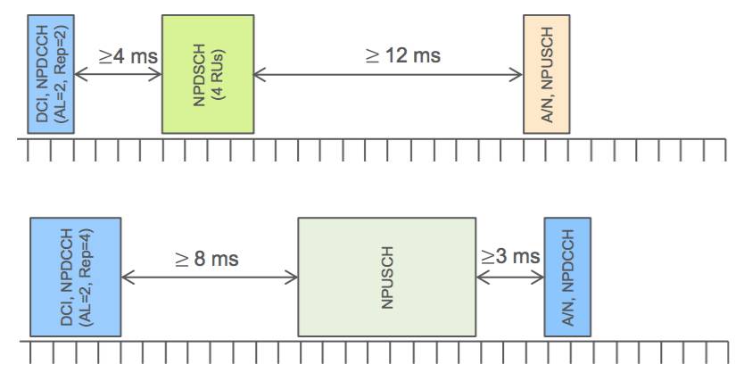
In the example above, the scheduling command is transmitted via DCI carried on NPDCH, with NPDCH using AL (aggregation levels) 1 or AL2 to transmit DCI. For AL1, two DCIs are reused in one subframe; otherwise, one subframe only carries one DCI (i.e., AL-2) to reduce coding rates and improve coverage. By enhancing coverage through retransmission, each retransmission occupies one subframe.
DCI can be used to schedule downlink or uplink data.
For scheduling downlink data, the DCI indicates the precise time offset between NPDCCH and the associated NPDSCH. Considering the limited computational capacity of IoT devices, the time offset between the end of NPDCCH and the start of the associated NPDSCH must be at least 4 ms.
After receiving NPDSCH, the terminal needs to use NPUSCH Format 2 to feedback the HARQ acknowledgment. The DCI indicates the resources of NPUSCH carrying the HARQ acknowledgment message. Considering the limited computational capacity of IoT devices, the time offset between the end of NPDSCH and the start of the HARQ acknowledgment must be at least 12 ms.
For uplink scheduling and HARQ operations, the time offset between the end of NPDCCH and the start of the associated NPUSCH must be at least 8 ms. After completing the NPUSCH transmission, the UE monitors NPDCCH to confirm whether the base station has correctly received NPUSCH or needs to retransmit.
6
Summary
Finally, let’s summarize some of the performance aspects of NB-IoT.
1) Peak Data Rate
The maximum TBS is 680 bits, lasting 3 ms, thus the peak physical layer rate of NDSCH is 680 bits/3 ms = 226.7 kbps. Similarly, the peak data rate of NPUSCH is 1000 bits/4 ms = 250 kbps. However, considering DCI, time offsets between NPDSCH/NPUSCH and HARQ acknowledgment, both downlink and uplink peak throughput are lower than these values.
2) Coverage
NB-IoT achieves a maximum coupling loss (MCL) that is 20 dB higher than LTE Rel-12. The enhancement in coverage is achieved by increasing the number of retransmissions, which reduces data rates. By introducing single subcarrier NPUSCH transmission and π/2-BPSK modulation to maintain a PAPR close to 0 dB, it reduces coverage impact due to power amplifier (PA) power back-off, ensuring enhanced coverage. With maximum retransmissions (128) and the lowest modulation and coding scheme, the physical layer rate of single-frequency NPUSCH is approximately 20 bps. With maximum retransmissions (512) and the lowest modulation and coding scheme for NPDSCH, the physical layer rate can reach 35 bps. These configurations approach a coupling loss of 170 dB, while LTE R12’s maximum is approximately 142 dB.
3) Device Complexity
To reduce terminal complexity, NB-IoT is designed as follows:
● Significantly reduced transmission block sizes for both downlink and uplink.
● Downlink supports only one redundant version.
● Only single-stream transmission is supported for both downlink and uplink.
● Terminals only need a single antenna.
● Only one HARQ process is supported for both downlink and uplink.
● Terminals do not require turbo decoders.
● Mobility measurements in disconnected mode, terminals only need to perform mobility measurements in idle mode.
● Low bandwidth, low sampling rate.
● Only FDD half-duplex is supported.
4) Latency and Battery Life
NB-IoT is mainly targeted at latency-insensitive applications; however, for applications such as sending alarm signals, NB-IoT supports latencies of less than 10 seconds. For terminals with 164 dB coupling loss, transmitting 200 bytes of data daily can achieve a battery life of up to 10 years.
5) Capacity
NB-IoT, with only one PRB resource, supports connections for 52,500 terminals per cell. In addition, NB-IoT supports multi-carrier operation. Therefore, capacity can be increased by adding NB-IoT carriers.
Alright, come on, strangle me….


References:
NB-IOT, Antti Ratilainen
A Primer on 3GPP Narrowband Internet of Things (NB-IoT), Y.-P. Eric Wang, Xingqin Lin, Ansuman Adhikary, Asbjörn Grövlen, Yutao Sui, Yufei Blankenship, Johan Bergman, and Hazhir S. Razaghi, Ericsson Research, Ericsson AB
LoRa and NB-IoT, Gagan Gupta, Darshan Patil
NB-IoT Solutions, Huawei
LTE Signaling for IoT, Anhar Al-Ansi
Some images source: ROHDE&SCHWARZ, China Mobile, Huawei, Intel, AT&T, NTT
Network Optimization Mercenaries Submission Email: [email protected]
Long press the QR code to follow

On the communication road, let’s walk together!