Source: Network Technology Alliance
Hello, this is the Network Technology Alliance, I am Rui Ge!
In modern data center network design, achieving high availability and high performance is an important challenge that every network engineer must face. As business demands continue to grow and network architectures become more complex, traditional single-device solutions are increasingly unable to meet these needs. Thus, two horizontal virtualization technologies, stacking and Multichassis Link Aggregation Group (M-LAG), have emerged.
As important technical means to achieve terminal redundancy access and link redundancy backup, both stacking and M-LAG can significantly improve the reliability and scalability of data center networks. However, despite their many similarities, they have their own advantages and disadvantages and applicable scenarios in practical applications. This article will delve into the basic principles, technical characteristics, advantages and disadvantages of stacking and M-LAG, and through detailed comparisons, help you make the best choice in specific network environments.
Stacking Technology
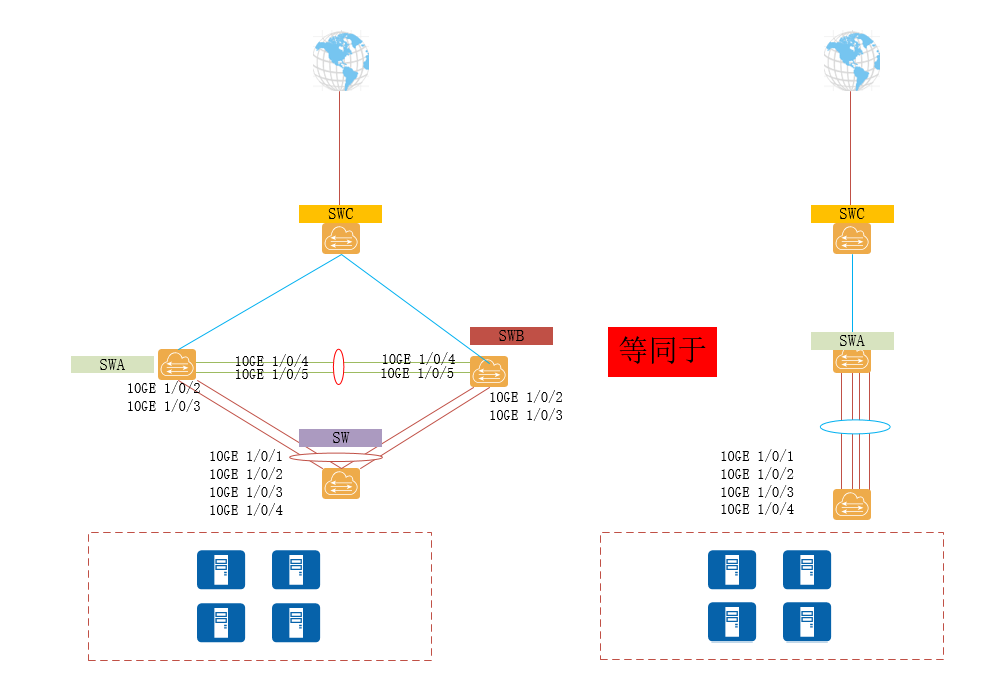
Stacking technology refers to the combination of multiple stacking-capable devices into a single logical device. Users can manage and use these devices as a single device. This method allows for the expansion of port numbers and switching capacity by adding devices, while also enhancing the reliability of the devices through mutual backup among multiple devices.
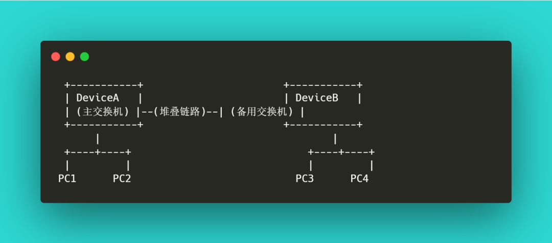
As shown in the figure, DeviceA and DeviceB are connected together via stacking links, logically forming a single device and participating in data forwarding as a whole.
Advantages and Disadvantages of Stacking Technology
Advantages
- Simplified Management: The stacking system requires only one IP address for management, reducing management complexity. Administrators can configure and monitor the entire stacking system through a single interface.
- Increased Port Density: Multiple switches combined together provide more ports, meeting the needs of large-scale networks.
- Seamless Redundancy: If any member in the stack fails, other members can seamlessly take over, ensuring high availability of the network.
- Enhanced Performance: Stacking increases the interconnect bandwidth between switches, improving data exchange efficiency and performance.
Disadvantages
- Limited Scalability: The number of stacked devices usually has an upper limit, and different manufacturers have different stacking limits, which may not meet large-scale expansion needs.
- Single Point of Failure: Although stacking improves system reliability, a failure of the master switch may lead to performance degradation or management interruption of the entire stacking system.
- Performance Bottleneck: The bandwidth of the stacking link may become a bottleneck, especially in high-traffic environments, potentially affecting the performance of the entire stacking system.
Working Principle of Stacking
The stacking system connects multiple physical switches together through dedicated stacking links, forming a logical switch. Typically, there is one master switch and several backup switches in the stacking system. The master switch is responsible for managing the entire stacking system, including configuration synchronization, fault detection, and recovery functions.
Master-Backup Switching
In the stacking system, if the master switch fails, the backup switch will immediately take over its management functions, ensuring normal network operation. This design enhances the redundancy and reliability of the system.
Data Forwarding
Data forwarding in the stacking system is performed by all member switches. Data packets can enter the stacking system through any switch and reach their destination via the optimal path. This design optimizes network traffic and reduces latency.
Configuration Synchronization
All switches in the stacking system share the same configuration file. When an administrator makes configuration changes on the master switch, these changes are automatically synchronized to all member switches, simplifying management operations.
M-LAG Technology
M-LAG (Multichassis Link Aggregation Group) is an emerging cross-device link aggregation technology. Its basic idea is to allow two access switches to negotiate link aggregation with the connected devices in the same state, making it appear to the connected devices as if a link aggregation relationship has been established with a single device. Through cross-device link aggregation, reliability can be improved from the board level to the device level.
Working Principle of M-LAG
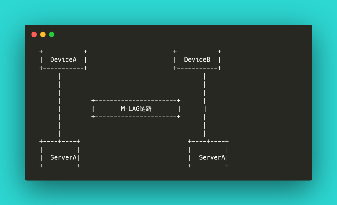
As shown in the figure, M-LAG is deployed between DeviceA and DeviceB, and the M-LAG devices negotiate link aggregation with ServerA through cross-device link aggregation, achieving dual access for ServerA.
In this topology:
-
M-LAG Link Aggregation Negotiation:
- DeviceA and DeviceB synchronize their states through the M-LAG protocol and negotiate link aggregation with ServerA.
- ServerA establishes physical connections with DeviceA and DeviceB, but logically these links are viewed as a single aggregation group.
Traffic Forwarding and Load Sharing:
- DeviceA and DeviceB share the load and jointly perform traffic forwarding.
- Through M-LAG, traffic is distributed between the two devices, optimizing the utilization of network resources.
Fault Recovery:
- When DeviceA or DeviceB fails, the M-LAG protocol can quickly switch traffic to the other device, ensuring normal business operation.
- This design enhances the reliability and availability of the network.
Advantages of M-LAG
Increased Reliability
M-LAG improves reliability from the board level to the device level through cross-device link aggregation. This means that even if one switch fails, the other switch can still maintain network connectivity, providing seamless failover.
Load Balancing
M-LAG can achieve load sharing between multiple devices, optimizing the distribution of network traffic and preventing a single device from becoming a bottleneck, thus improving overall network performance.
Simplified Management
Compared to stacking technology, M-LAG is simpler during upgrades and maintenance. Stacking systems typically require the entire stacking system to reboot simultaneously during firmware upgrades, while M-LAG allows for upgrades on a per-device basis, reducing the risk of network interruptions.
Compatibility and Scalability
M-LAG has better compatibility and scalability, allowing link aggregation negotiations with devices from different manufacturers, adapting to diverse network environment needs.
Comparison of Stacking and M-LAG
Reliability
Stacking
- Centralized Control Plane: In a stacking system, all switches share a control plane. The master switch is responsible for controlling the entire stacking system. If the master switch fails, although the backup switch will take over, the failure may still affect the entire stacking system.
- Device-Level, Board-Level, and Link-Level Reliability: Stacking provides a certain redundancy mechanism but mainly relies on the health status of the master switch.
M-LAG (Recommended)
- Independent Control Plane: In an M-LAG system, each switch has an independent control plane. Even if one switch fails, the other can still operate normally, isolating the fault domain.
- Device-Level, Board-Level, and Link-Level Reliability: M-LAG provides higher reliability through cross-device link aggregation, ensuring business continuity.
Configuration Complexity
Stacking
- Simple: The stacking system logically behaves as a single device, and configuration applies to all member devices, simplifying management and configuration.
M-LAG (Recommended)
- Simple: The M-LAG system requires separate configuration for two devices, but with modern management tools and automation scripts, the configuration process remains straightforward.
Cost
Stacking
- Moderate: Stacking requires dedicated stacking cables, which add to hardware costs.
M-LAG (Recommended)
- Moderate: M-LAG requires the deployment of peer-link connections, which have costs similar to stacking cables.
Performance
Stacking
- Moderate: The control plane of the master switch needs to handle the forwarding plane of all member switches, increasing the CPU load on the master switch, which may affect system performance.
M-LAG (Recommended)
- High: Each switch in M-LAG independently handles data forwarding, sharing the CPU load and improving overall performance.
Upgrade Complexity
Stacking
- High: Stacking systems can reduce business interruption time through quick upgrades, but the upgrade operation takes longer and carries higher risks, requiring synchronization of all member devices.
M-LAG (Recommended)
- Low: In M-LAG systems, each device can be upgraded independently, reducing the complexity and risk of upgrade operations.
Upgrade Interruption Time
Stacking
- Relatively Long: Under typical configurations, the upgrade interruption time for stacking systems ranges from 20 seconds to 1 minute, depending on the business volume.
M-LAG (Recommended)
- Short: During upgrades, the interruption time for M-LAG systems is usually within seconds, with minimal impact on business.
Network Design
Stacking
- Relatively Simple: Stacking devices logically behave as a single device, resulting in a simpler network structure that is easier to manage and design.
M-LAG (Recommended)
- Relatively Complex: M-LAG devices are still logically two independent devices, resulting in a more complex network structure that requires more planning and management.
Applicable Scenarios
Stacking
- Suitable for scenarios where there are no strict requirements on software version upgrade interruption time and where network maintenance is simple.
- Suitable for small to medium-sized networks with lower device quantity and scalability requirements.
M-LAG (Recommended)
- Suitable for scenarios with high requirements for business interruption time during software version upgrades and higher network reliability requirements.
- Suitable for large networks or critical business environments that can accept a certain degree of maintenance complexity.
To help everyone remember, Rui Ge has summarized the above comparisons into a table:
| Comparison Dimension | Stacking | M-LAG (Recommended) |
|---|---|---|
| Reliability | Moderate: Centralized control plane, failures may spread to member devices | Higher: Independent control plane, fault domain isolation |
| Configuration Complexity | Simple: Logically a single device | Simple: Two devices independently configured |
| Cost | Moderate: Requires deployment of stacking cables | Moderate: Requires deployment of peer-link connections |
| Performance | Moderate: Heavy load on master switch control plane | High: Member switches independently forward, CPU load remains unchanged |
| Upgrade Complexity | High: Long upgrade operation time, high risk | Low: Devices can be upgraded independently, upgrade operation is simple, low risk |
| Upgrade Interruption Time | Relatively Long: 20 seconds to 1 minute | Short: Seconds-level interruption |
| Network Design | Relatively Simple: Logically a single device | Relatively Complex: Logically two devices |
| Applicable Scenarios | No requirements for software version upgrade interruption time, simple network maintenance | High requirements for business interruption time during software version upgrades, high network reliability |
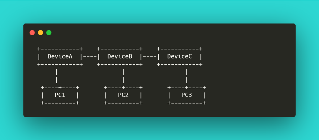
DeviceA, DeviceB, and DeviceC are connected via stacking cables, forming a logical device, simplifying management but relying on the health status of the master switch.
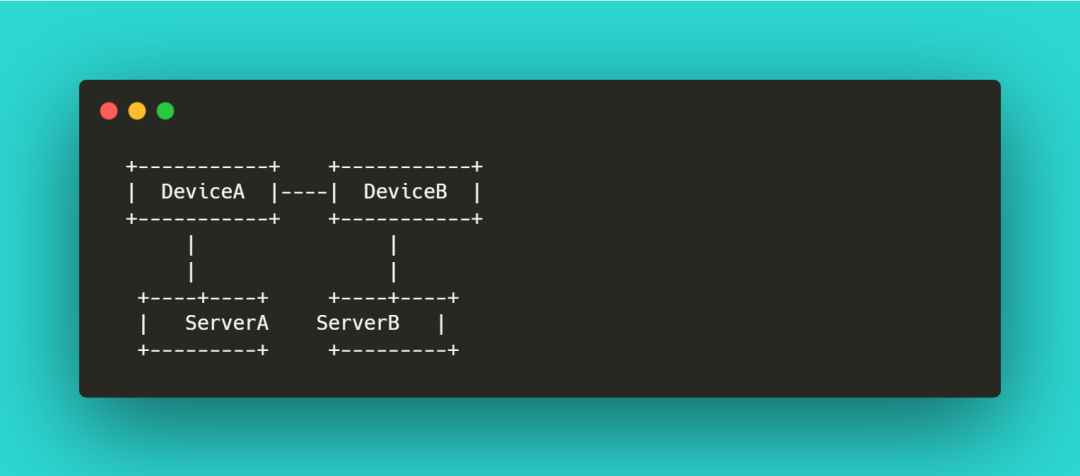
DeviceA and DeviceB are connected via M-LAG links, achieving dual access for ServerA and ServerB. Each device independently controls, improving system reliability and performance.
Previous Recommendations
Illustration of the OSI Seven-Layer Model, the strongest popular science of 2024!
What are the differences between VLAN and SVI, both of which can segment networks and manage traffic?
Three types of wireless APs: panel AP, ceiling-mounted AP, outdoor AP
Three major PoE standards: IEEE 802.3af, IEEE 802.3at, IEEE 802.3bt
What is a private IP address? What are the ranges of private IP addresses?