 IntroductionFor embedded product development, cost is the most fundamental consideration. Even if the conclusions are similar for the same problem, they often have completely different paths in different contexts. Take the question of whether “JPEG software decoding on the Cortex-M platform is meaningful” as an example; the thought process here is quite typical:First, the Cortex-M platform spans a wide range of processors from Cortex-M0 to Cortex-M85. Generally, we classify most Cortex-M0/M0+ and some Cortex-M3 chips as “Deep Embedded Systems“—this term is actually a high-context way of saying “resource-constrained” or “cheap goods”. Their common characteristics are:
- Frequency below 72MHz (for example, common Cortex-M0+ chips mostly operate at 48MHz or 64MHz);
- Flash is limited (128K is considered a large family, 64K is common, and 32K is quite common);
- SRAM is barely sufficient (starting from 6K, 8K is playable, 12K is standard, and if there is 16K, engineers celebrate);
- In terms of performance, due to the “purely decorative” role of on-chip Flash Cache, they are basically “crippled versions”. For example, Arm officially states that the maximum Coremark for Cortex-M0+ is 2.46, but in practice, these chips often only score around 0.6 ~ 1.2 when running on Flash.
At this point, some friends may feel dissatisfied: the official value is a theoretical maximum, the Coremark limit achieved under ideal conditions on an FPGA. Actual products run on Flash, so how can we achieve such good results?Some can, my friend, some can. For example, the RP2040 can achieve 90% of the official limit—2.32—when running Coremark on externally connected SPI Flash in XIP mode.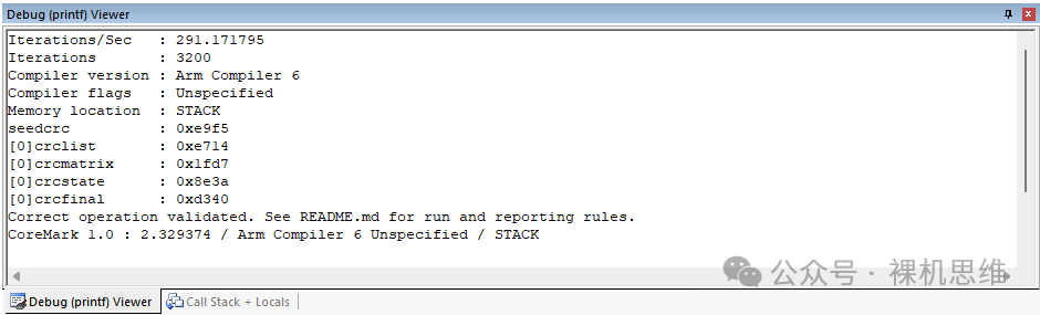 Project link:https://github.com/GorgonMeducer/Pico_TemplateFor those with questions about running Coremark, you can refer to the article “Not Convinced? Run a Benchmark!—Coremark Edition“; I won’t elaborate further here.Another category represented by Cortex-M3/Cortex-M4 and the increasingly popular Cortex-M33 (or STAR-MC1) is referred to as “Mainstream Embedded“. Their characteristics are:
- Frequencies usually above 72MHz, with common frequencies being 96MHz, 144MHz, and 216MHz;
- Moderate Flash size: starting from 128K, 256K is common, and many can even reach the threshold of 512K;
- SRAM focuses on “cost-effectiveness”: 32K is the starting point, 64K is passing, and 128K is the favorite of engineers.
- In terms of performance, due to the common configuration of 8~16K Flash Cache, even when the system clock frequency is much higher than the Flash frequency (usually within 28MHz to 32MHz), they can still achieve 60% to 90% of the official performance of Cortex-M4F.
Because of these characteristics, these chips are moderately priced, resource-rich, and perform just right, making them widely used in various embedded product developments. For many products driving color LCDs, they are even the “starting point for selection”.The last category of products is referred to as “Flagship Embedded“, represented by Cortex-M7, Cortex-M85, and the recently popular Cortex-M55. Due to their rich resources and excellent performance—being MCUs that touch the lower limits of MPUs—they are also highly publicized as “Cross-boundary Processors“. Their characteristics are:
- Very high frequencies: starting from 216MHz, common at 480MHz, and 1G or even 1.5GHz is not uncommon.
- Generous Flash: starting from 1MByte, 2MByte is standard, and 4MByte is common.
- Diverse RAM combinations: 1M SRAM, 32M SDRAM, and various auxiliary PSRAM, etc.
- Performance focuses on “powerful execution”—without optimization, software still runs smoothly.
 Before you think I am “digressing”, let’s return to the question posed at the beginning of the article: “Is JPEG software decoding meaningful on the Cortex-M platform?“
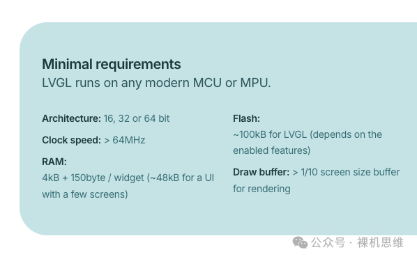
- For most GUI applications, the starting point for system selection is represented by the “mainstream embedded systems” like Cortex-M4F, such as the STM32F4 series (and its compatible chips). The culprit for this is LVGL—currently the de facto “free lunch” solution, which has its minimum requirements just within the range of “mainstream embedded” microcontrollers.
- Decoding JPG images at runtime has certain performance requirements for the system—taking a 10K size 320*240 image as an example, to achieve a frame rate of 3 FPS, the basic requirement for the system is at least Cortex-M3 at 72MHz.
- As is well known, according to the description in the “Arm-2D tutorial”: if you have sufficient resources, be sure to choose a standard GUI protocol stack for GUI development, such as LVGL; for a few resource-constrained environments (whether the chip itself is resource-constrained or the resources left for GUI development after excluding other applications are constrained), if the GUI interface is relatively simple, then Arm-2D can be used to reduce product costs.
- Mainstream embedded systems and flagship embedded systems often come with JPEG hardware decoders. Even without a decoder, under the drive of high-performance processors, software decoding can still yield acceptable results.
The conclusion seems to be clear:
- If you choose a mainstream embedded system (or flagship system), then whether you choose hardware decoding or TJpgDec software decoding, using JPEG in the GUI to save memory resources is a good choice;
- If you choose a deep embedded system (almost no chips in this category provide JPEG hardware decoders), it is not suitable for GUI development (basically saying goodbye to LVGL). Even if you use Arm-2D to achieve simple graphical applications, the computing power provided by the CPU for JPEG decoding can only provide an effect akin to “stuttering like a PPT”. In such conditions, what practical significance does using JPEG have?
 Don’t rush to conclusions. If you must perform JPEG decoding in a deep embedded system, we can extract the following characteristics:
- Low Flash consumption (for a 320*240 image at 75%~80% quality, the typical size of a jpg image is around 10K, and the few background images required by the application can be stored directly in internal Flash (no external expansion needed).
- Slow decoding speed, basically around 1 ~ 0.5FPS.
- If using TJpgDec for decoding, it also has the advantages of small code size, low RAM consumption (within 3200Bytes), and no need to cache the entire frame image (decode and display simultaneously).
So are there application products that have almost no requirements for frame rate but are extremely sensitive to memory consumption (cost-sensitive) and have certain graphical interface requirements? Actually, there are many:
- Dashboards with relatively complex backgrounds
- Simple GUI products that occasionally need to display company logos
- Electronic tags
- Various small products that can afford to stutter like a PPT, such as electronic tags (e-ink screens), cultural and creative products that just need to display images, toys, small appliances, etc.
 In fact, there is another situation that is often overlooked: when we develop using mainstream embedded chips, the Flash and SRAM resources left for the GUI are nearly depleted. Even without the help of hardware JPEG decoders, storing JPEG resource images is still a good choice to save Flash (avoiding external Flash expansion).Considering the high CPU frequency, we can even achieve relatively smooth animation effects.
 In summary: when we are forced to use Arm-2D for embedded application development in resource-constrained environments, “doing some JPEG soft decoding is quite necessary!“.
 How to Deploy TJpgDec Decoder in Arm-2DStarting from v1.2.2, Arm-2D integrates TJpgDec—a small resource JPEG decoding library that spans 8bit, 16bit, and 32bit platforms.The native TJpgDec only consumes 3200Bytes of RAM as “Working Memory” to support JPEG image decoding of any resolution and allows output in 8bit, 16bit (RGB565), and 24bit (RGB888) formats.Of course, TJpgDec also has some limitations, such as not supporting 32bit (Arm-2D’s CCCN888) format, not supporting decoding only the “Region of Interest (ROI)” we are interested in, and not supporting swapping the red and blue channels, etc. Arm-2D has made modifications to TJpgDec to achieve the following functionalities:
- Automatically set the output format based on Arm-2D’s color depth (__GLCD_CFG_COLOUR_DEPTH__) (and added support for 32bit output format);
- Added ROI functionality—supports PFB, supports dirty matrix;
- Allows users to enhance ROI decoding performance by adding reference points;
- On-demand decoding, no need to fully decode the entire image and then save it to RAM;
- In copy-only mode, no need for (other than working buffer) pixel buffer;
- JPEG images participate in ordinary Arm-2D API operations in tile form.
Arm-2D introduces TJpgDec in the form of a Loader, so when deploying, we need to check Acceleration::Arm-2D Extras::Loaders in the RTE window, as shown in the figure below:After clicking “OK”, RTE will automatically add three files to the Acceleration list in the project manager:
- tjpgd.c: the modified source file of TJpgDec
- tjpgd_loader.c: the source file of the TJpgDec Loader introduced by Arm-2D
- arm_tjpgd_cfg.h: the configuration header file introduced by Arm-2D (generally no modifications are needed)
Thus, we have completed the deployment of the TJpgDec Loader. How to Obtain JPEG Images that Meet RequirementsThe JPEG algorithm has two modes when compressing images: one is the “baseline” mode that requires strict “sequential” decoding, and the other is the “advanced” mode that supports “thumbnails”. Due to its positioning, the compact TJpgDec only supports the baseline mode, so most JPEG images available on the market must be converted to be usable.There are many methods to achieve transcoding; for example, I use the command line on MacOS:
convert input.jpg -quality 95 -interlace none output.jpgHere, the -interlace none parameter ensures that the JPEG image uses baseline encoding.Other transcoding methods can be inquired from Kimi or DeepSeek:
How to convert an image to a JPEG image using baseline encoding?We won’t elaborate further here.Once we have a baseline encoded jpg image, the next step is to convert it into a C language array—so it can be integrated as a resource into the project. There are many tools online for converting binary data (files) to C language arrays (Binary to C), for example:https://notisrac.github.io/FileToCArray/After opening, you can see an interface like this:According to the instructions in the image, click “Select File” to open the target jpg file, and you can see the content below:Here, we need to check the options as indicated in the image, and finally click Convert to obtain the required C language array:At this point, you can either click “Copy to Clipboard” to copy the array to an existing C file or click “Save as file” to save the array. After completing the above steps, we need to make a small modification to the generated array—fill in the file size as a comment in the array declaration, for example:
// array size is 23656const uint8_t Helium[23656] = { ...}If you are a perfectionist, you can also modify the name according to your coding standards and add the original declaration of the array for convenience:
extern const uint8_t c_jpgHelium[23656];// array size is 23656const uint8_t c_jpgHelium[23656] = { ...}How to Use TJpgDec Loader in a SceneFirst, find a class for a scene and add an arm_tjpgd_loader_t object, for example:
/*! * \brief a user class for scene tjpgd */typedef struct user_scene_tjpgd_t user_scene_tjpgd_t;struct user_scene_tjpgd_t { implement(arm_2d_scene_t); //! derived from class: arm_2d_scene_tARM_PRIVATE( ... arm_tjpgd_loader_t tJPGBackground; ...) /* place your public member here */};Next, we need to add the initialization code for the arm_tjpgd_loader_t object in the scene’s initialization function:
ARM_NONNULL(1)user_scene_tjpgd_t *__arm_2d_scene_tjpgd_init( arm_2d_scene_player_t *ptDispAdapter, user_scene_tjpgd_t *ptThis){ ... *ptThis = (user_scene_tjpgd_t){ ... }; /* ------------ initialize members of user_scene_tjpgd_t begin ---------------*/ /* initialize TJpgDec loader */ do { ... arm_tjpgd_loader_cfg_t tCFG = { .bUseHeapForVRES = true, .ptScene = (arm_2d_scene_t *)ptThis, .u2WorkMode = ARM_TJPGD_MODE_PARTIAL_DECODED, ... }; arm_tjpgd_loader_init(&this.tJPGBackground, &tCFG); } while(0); /* ------------ initialize members of user_scene_tjpgd_t end ---------------*/ arm_2d_scene_player_append_scenes( ptDispAdapter, &this.use_as__arm_2d_scene_t, 1); return ptThis;}Here, the initialization function arm_tjpgd_loader_init() accepts a structure of type arm_tjpgd_loader_cfg_t to pass initialization information. Its definition is as follows:
typedef struct arm_tjpgd_loader_cfg_t { //arm_2d_size_t tSize; uint8_t bUseHeapForVRES : 1; uint8_t u2ScratchMemType : 2; uint8_t u2WorkMode : 2; uint8_t : 5; struct { const arm_tjpgd_loader_io_t *ptIO; uintptr_t pTarget; } ImageIO; arm_2d_scene_t *ptScene;} arm_tjpgd_loader_cfg_t;Where:
- u2WorkMode is used to specify the working mode of the decoder, with the default value being:
ARM_TJPGD_MODE_PARTIAL_DECODED, indicating on-demand decoding, which is also the most commonly used mode;
-
TJpgDec Loader is essentially a virtual resource, so except for the “background image loading mode” that works with Copy-Only, it requires a pixel buffer not larger than PFB during operation.In the aforementioned “on-demand decoding mode“, when bUseHeapForVRES is set to “false(0)“, TJpgDec Loader will request PFB as the pixel buffer. When bUseHeapForVRES is set to true(1), TJpgDec Loader will request the buffer from Heap through __arm_2d_allocate_scratch_memory().
-
When TJpgDec Loader allocates resources as a pixel buffer from __arm_2d_allocate_scratch_memory(), we can specify the speed attributes of the required storage space through u2ScrachMemType:
typedef enum { ARM_2D_MEM_TYPE_UNSPECIFIED, //!< speed is arbitrary, use whatever is available ARM_2D_MEM_TYPE_SLOW, //!< slower RAM //!< for slow memories, such as SDRAM, DDRAM, external memory etc ARM_2D_MEM_TYPE_FAST, //!< fast RAM //!< for fast memories, such as TCM, SRAM etc.} arm_2d_mem_type_t;Generally, this attribute can remain at its default value.
-
ptScene: points to the scene class where TJpgDec Loader resides.
Each TJpgDec Loader requires an IO interface object to access the JPG data stream. Since we are using a C array to store the jpg image, we need to add a dedicated read/write IO object arm_tjpgd_io_binary_loader_t in the scene template class:
/*! * \brief a user class for scene tjpgd */typedef struct user_scene_tjpgd_t user_scene_tjpgd_t;struct user_scene_tjpgd_t { implement(arm_2d_scene_t); //! derived from class: arm_2d_scene_tARM_PRIVATE( ... arm_tjpgd_loader_t tJPGBackground; union { arm_tjpgd_io_binary_loader_t tBinary; } LoaderIO; ...) /* place your public member here */};Before using this IO interface, it needs to be initialized:
extern const uint8_t c_chHelium[23656];arm_tjpgd_io_binary_loader_init( &this.LoaderIO.tBinary, c_chHelium75JPG, sizeof(c_chHelium75JPG));Then pass it as part of the arm_tjpgd_loader_cfg_t object to arm_tjpgd_loader_init():
/* initialize TJpgDec loader */do { extern const uint8_t c_chHelium[23656]; arm_tjpgd_io_binary_loader_init( &this.LoaderIO.tBinary, c_chHelium75JPG, sizeof(c_chHelium75JPG)); arm_tjpgd_loader_cfg_t tCFG = { ... .ImageIO = { .ptIO = &ARM_TJPGD_IO_BINARY_LOADER, .pTarget = (uintptr_t)&this.LoaderIO.tBinary, }, ... }; arm_tjpgd_loader_init(&this.tJPGBackground, &tCFG);} while(0);Thus, we have completed the initialization of the TJpgDec Loader.Next, we need to insert the following functions into the corresponding time handlers of the scene template:For example:
static void __on_scene_tjpgd_load(arm_2d_scene_t *ptScene){ user_scene_tjpgd_t *ptThis = (user_scene_tjpgd_t *)ptScene; ARM_2D_UNUSED(ptThis); arm_tjpgd_loader_on_load(&this.tJPGBackground);}...static void __on_scene_tjpgd_depose(arm_2d_scene_t *ptScene){ user_scene_tjpgd_t *ptThis = (user_scene_tjpgd_t *)ptScene; ARM_2D_UNUSED(ptThis); arm_tjpgd_loader_depose(&this.tJPGBackground); ...}...static void __on_scene_tjpgd_frame_start(arm_2d_scene_t *ptScene){ user_scene_tjpgd_t *ptThis = (user_scene_tjpgd_t *)ptScene; ARM_2D_UNUSED(ptThis); arm_tjpgd_loader_on_frame_start(&this.tJPGBackground);}...static void __on_scene_tjpgd_frame_complete(arm_2d_scene_t *ptScene){ user_scene_tjpgd_t *ptThis = (user_scene_tjpgd_t *)ptScene; ARM_2D_UNUSED(ptThis); arm_tjpgd_loader_on_frame_complete(&this.tJPGBackground);}Thus, we have completed all the preparatory work. Everything is a TileAs per the design philosophy of Arm-2D, almost all API operation objects are “tiles”—the jpg images loaded on demand by TJpgDec Loader are no exception. Below, we will demonstrate how to use TJpgDec Loader by showing an image in the center of a scene:
staticIMPL_PFB_ON_DRAW(__pfb_draw_scene_tjpgd_handler){ ARM_2D_PARAM(pTarget); ARM_2D_PARAM(ptTile); ARM_2D_PARAM(bIsNewFrame); user_scene_tjpgd_t *ptThis = (user_scene_tjpgd_t *)pTarget; arm_2d_canvas(ptTile, __top_canvas) { /*-----------------------draw the foreground begin-----------------------*/ /* following code is just a demo, you can remove them */ arm_2d_align_centre( __top_canvas, this.tJPGBackground.vres.tTile.tRegion.tSize) { arm_2d_tile_copy_only( &this.tJPGBackground.vres.tTile, ptTile, &__centre_region); } /*-----------------------draw the foreground end -----------------------*/ } ARM_2D_OP_WAIT_ASYNC(); return arm_fsm_rt_cpl;}Here, since TJpgDec Loader is essentially a virtual resource—derived from the base class arm_2d_tile_t—we can use it directly as a tile:
- By using this.tJPGBackground.vres.tTile.tRegion.tSize to get the size of the image and using arm_2d_align_centre() to center the image;
- By using arm_2d_tile_copy_only() in background image loading mode (no additional pixel buffer needed) to display the jpg image on the screen.
Isn’t it very simple?The following image shows the effect of the TJpgDec Loader running in the PC example project:If you cannot display the image using the above method, you can check the following two directions:
- Ensure that the size of the system Heap is not less than 4K—ensuring that the 3200 bytes of Working Memory can be successfully allocated.
- Temporarily use only arm_2d_tile_copy_only() for testing—avoiding additional pixel buffer allocation.
- Ensure that the image you are using is encoded using baseline.
For safety, arm-2d provides several jpg image arrays for verification:
extern const uint8_t c_chHeliumJPG[23656]; //! 95% qualityextern const uint8_t c_chHelium75JPG[10685];//! 75% qualityextern const uint8_t c_chHelium30JPG[5411]; //! 30% qualityTwo Scene Templates, Two DemosIf the above methods do not solve the problem, or if you are unsure about the code you added, or if you just want to quickly evaluate the effect of JPG decoding, Arm-2D has prepared two demos that can be used with just a checkbox:
- Decoding JPG with TJpgDec
This demo displays a 320 * 256 jpg image centered using full-screen refresh.The following image shows the effect of the TJpgDec Loader running in the PC example project:You can use this scene to evaluate the JPEG decoding performance that the current hardware system can achieve in the extreme full-screen refresh mode. Generally, this performance is the worst-case scenario for the current chip—because usually, we will use a dirty matrix—only refreshing the areas on the screen that change to optimize frame rate. For more on using dirty matrices, please refer to the article “How to Use Dirty Matrices to Optimize Frame Rate (Basic Edition)” in the Arm-2D list; I won’t elaborate further here.
- Showing Animation with TJpgDec
This demo displays a GIF-like animation effect in the center of the screen by decoding JPEG. Since dirty matrices are used, the frame rate of the scene is independent of the screen resolution, making it suitable for evaluating the current platform’s ability to display animations using JPG.The following video shows the effect of RP2040 (Cortex-M0+) displaying the famous “Telecom Fraud” GIF at 240 * 240 via SPI interface.In addition to the ready-to-use demos, from a practical perspective, cmsis-pack also provides us with project templates related to MDK for TJpgDec Loader—with just a few modifications (like replacing materials), you can complete the design of a class of application scenarios.They are:
- Meter: an instrument application using jpg as the dial background
- Histogram: a dynamic bar chart display application using jpg as the background
Now, let’s take the Meter as an example to demonstrate the process of adding the scene template:1. In the project manager, select the Group where you want to add the code template, right-click to bring up the menu: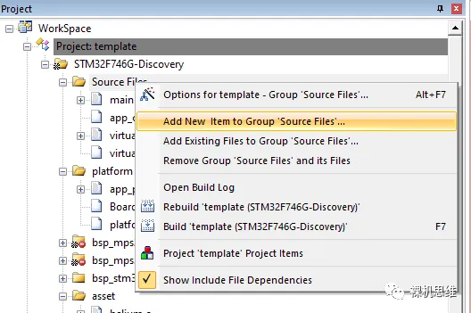
2. Select Add New Item to Group.
3. In the window, find User Code Template. Expand Acceleration, select Arm-2D Helper:PFB‘s Scene Template Meter, and in the “Location” field, click the “…” button to add the example template to the project directory.

4. In the MDK project configuration, add a search path for the header files to point to the directory where arm_2d_scene_meter.h is located.
5. In main.c, add the header file:
#include "arm_2d_scene_meter.h"Thus, we can add arm_2d_scene_meter to the scene player through the corresponding initialization code, for example:
...arm_2d_scene_meter_init(&DISP_ADAPTER0);arm_2d_scene_player_switch_to_next_scene(&DISP0_ADAPTER);...6. Open arm_2d_scene_meter.h, find the macro, and set it to “1” to choose to use jpg as the background image:
#ifndef ARM_2D_SCENE_METER_USE_JPG# define ARM_2D_SCENE_METER_USE_JPG 1#endifThe effect is as follows: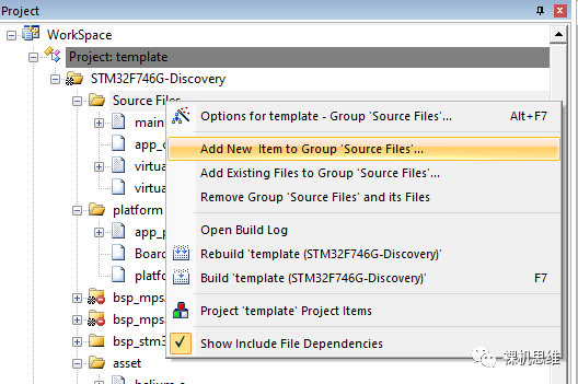 Similarly, we can also choose to add Histogram to the project using the template:Note that the macro used to enable jpg decoding in arm_2d_scene_histogram.h is as follows:
#ifndef ARM_2D_SCENE_HISTOGRAM_USE_JPG# define ARM_2D_SCENE_HISTOGRAM_USE_JPG 1#endifThe running effect is as follows:It is worth noting that Histogram itself has very low performance requirements, but when you use jpg as the background image, the performance requirements suddenly increase. If you see effects like the one below (or even worse), it indicates that the performance of your hardware platform may be low:As a criterion, the higher the system performance, the longer the sine wave wavelength we see in Histogram; conversely, the lower the performance, the shorter the wavelength.How to Integrate with File SystemsWhen we can use jpg images in graphical applications, many clever friends may immediately think of “saving the resource files involved in the application in jpg format on an SD card or SPI Flash simulating a USB drive“. This way, updating resources does not require modifying the code (combined with Layout Assistant, it can achieve adaptive sizing of jpg images).In the previous examples, TJpgDec Loader accessed the jpg images in the array through the arm_tjpgd_io_binary_loader_t type interface object. In fact, Arm-2D also provides an interface class called arm_tjpgd_io_file_loader_t to facilitate accessing jpg images in the file system through the API functions in <stdio.h> (fopen, fread, fseek, and fclose). Its usage is very simple, for example:1. In the scene class, add a member of type arm_tjpgd_io_file_loader_t:
struct user_scene_tjpgd_t { implement(arm_2d_scene_t); //! derived from class: arm_2d_scene_tARM_PRIVATE( ... union { arm_tjpgd_io_file_loader_t tFile; } LoaderIO; ...) /* place your public member here */};2. In the scene initialization function, add the initialization for the arm_tjpgd_io_file_loader_t object:
arm_tjpgd_io_file_loader_init( &this.LoaderIO.tFile, "../common/asset/Helium.jpg");Here, we need to specify the detailed path of the jpg file.3. When initializing TJpgDec Loader, bind the object to ImageIO:
/* initialize TJpgDec loader */do { arm_tjpgd_loader_cfg_t tCFG = { ... .ImageIO = { .ptIO = &ARM_TJPGD_IO_FILE_LOADER, .pTarget = (uintptr_t)&this.LoaderIO.tFile, }, ... }; arm_tjpgd_loader_init(&this.tJPGBackground, &tCFG);} while(0);4. Ensure that the file access functions defined by stdio.h in your embedded system environment work correctly, i.e., we can correctly access files on the SD card or SPI Flash using fopen(), fread(), fseek(), and fclose(). In addition to accessing the file system through the standard functions provided by stdio.h, many friends will also use third-party libraries such as FatFS and littleFS. In this case, arm_tjpgd_io_file_loader_t will not meet the requirements.To integrate with these third-party libraries, we actually need to implement an interface called arm_tjpgd_loader_io_t:
typedef struct arm_tjpgd_loader_io_t { bool (*fnOpen)(uintptr_t pTarget, arm_tjpgd_loader_t *ptLoader); void (*fnClose)(uintptr_t pTarget, arm_tjpgd_loader_t *ptLoader); bool (*fnSeek)(uintptr_t pTarget, arm_tjpgd_loader_t *ptLoader, int32_t offset, int32_t whence); size_t (*fnRead)(uintptr_t pTarget, arm_tjpgd_loader_t *ptLoader, uint8_t *pchBuffer, size_t tSize);} arm_tjpgd_loader_io_t;In fact, from an object-oriented perspective, arm_tjpgd_loader_io_t is a definition of a virtual function table, a collection of methods for the IO class. In addition to implementing these methods, we also need to design an IO class for the file system we want to integrate with, such as the previously mentioned IO class arm_tjpgd_loader_file_t, which is defined as follows:
typedef struct arm_tjpgd_io_file_loader_t {ARM_PRIVATE( const char *pchFilePath; FILE *phFile; )} arm_tjpgd_io_file_loader_t;We can see that this class only saves the target file’s path (pchFilePath) and the handle after opening the file (phFile)—this is because most of the functionality required for file operations has already been completed through fopen, fseek, fread, and fclose.However, in some cases, such as the fnSeek corresponding to arm_tjpgd_loader_io_t, the read/write pointer positioning function is not implemented in third-party libraries (like fatfs), so we need to maintain a size_t type read/write pointer, for example, tPosition in arm_tjpgd_io_binary_loader_t:
typedef struct arm_tjpgd_io_binary_loader_t {ARM_PRIVATE( size_t tPostion; uint8_t *pchBinary; size_t tSize;)} arm_tjpgd_io_binary_loader_t;And implement the corresponding functionality:
staticbool __arm_tjpgd_io_binary_seek(uintptr_t pTarget, arm_tjpgd_loader_t *ptLoader, int32_t offset, int32_t whence){ arm_tjpgd_io_binary_loader_t *ptThis = (arm_tjpgd_io_binary_loader_t *)pTarget; ARM_2D_UNUSED(ptLoader); assert(NULL != ptThis); assert(NULL != this.pchBinary); assert(this.tSize > 0); switch (whence) { case SEEK_SET: if (offset < 0 || offset >= (int32_t)this.tSize) { return false; } this.tPostion = offset; break; ... case SEEK_CUR: if (offset > 0) { if ((this.tPostion + offset) >= this.tSize) { return false; } this.tPostion += offset; } else if (offset < 0) { size_t tABSOffset = -offset; if ((this.tPostion < tABSOffset)) { return false; } this.tPostion -= tABSOffset; } break; default: return false; } return true;}Here, it is important to emphasize that when we maintain the read/write position (tPosition) ourselves:
- In the implementation corresponding to fnSeek, both SEEK_SET and SEEK_CUR must be handled;
- fnOpen must reset the read/write position (tPosition) to “0“;
- fnRead must update the read/write pointer (tPosition) based on the actual amount of data read;
- tPosition is a size_t type variable, which is unsigned, so when processing negative offset, we need to handle the sign of offset.
For more details, please refer to the source code of arm_tjpgd_io_binary_loader_t and arm_tjpgd_io_file_loader_t (in tjpgd_loader.c and tjpgd_loader.h), we won’t elaborate further here.Performance Optimization TipsThe minimum unit for JPEG encoding and decoding is a small rectangle with both length and width being multiples of 8—common sizes are 8*8 pixels and 16*16 pixels. The encoded JPG image is actually composed of these small rectangles arranged from left to right, top to bottom in rows.In such a structure, if the data length corresponding to each small rectangle is the same, we can quickly locate the target small rectangle in the data stream based on the region of interest. However, due to the Huffman tree sorted encoding method used by JPEG, the encoding length corresponding to each small rectangle varies, which means that if we want to find the small rectangle corresponding to a certain coordinate in the middle of the image, we must decode all the previous small rectangles sequentially, as shown in the figure below:In addition, for the situation in the image below, after completing the decoding of the first row of the blue part, even if we want to fast forward to the position of the second row of blue, we must decode all the subsequent parts that are not needed sequentially before it is possible:These two situations lead to the almost unavoidable ineffective decoding phenomenon in ROI mode (only decoding the region of interest)—in other words, it means doing unnecessary work. To solve this problem, especially in conjunction with the use of dirty matrices, Arm-2D creatively introduced the concept of “decoding context“, which means:
- Record the context corresponding to the starting point of the target area during the first decoding process
- In subsequent decoding processes, you can directly start decoding from the context, thus skipping the previous “unnecessary work”.
To reduce the burden on users, Arm-2D will automatically add some contexts. Additionally, users can also add contexts for specified reference coordinates through the function arm_tjpgd_loader_add_reference_point(). This API has three prototypes:
/*! * \brief add reference point for a given TJpgDec Loader. * * \note Prototype 1: * arm_tjpgd_loader_add_reference_point( * <pointer to TJpgDec Loader object>, * <coordinates of the reference point in the JPG image>); * * \note Prototype 2: * arm_tjpgd_loader_add_reference_point( * <pointer to TJpgDec Loader object>, * <coordinates of the JPG image in a specific canvas> * <coordinates of the reference point in the same canvas>); * * \note Prototype 3: * arm_tjpgd_loader_add_reference_point( * <pointer to TJpgDec Loader object>, * <pointer to the target tile> * <coordinates of the JPG image in the target tile> * <absolute coordinates of the reference point on the screen>); */#define arm_tjpgd_loader_add_reference_point(__TJPGD_LD_PTR, ...) "Generally:
- If you want to specify a reference point inside the JPG image, use “Prototype 1”;
- If you are unsure whether the reference point is inside the JPG image, but know that both the JPG image and the reference point are located within a certain canvas, then just use “Prototype 2″—providing the position of the image within the canvas and the coordinates of the reference point within the canvas;
- If you only want to add a reference point for a specific absolute coordinate on the screen, regardless of the specific position of the JPG image, then use “Prototype 3” to meet this requirement.
 Additionally, based on previous conclusions, it is easy to find that if an image is wide (has a large width), it may lead to more unnecessary work when wrapping—this means that reducing the line width is very beneficial for improving decoding performance in ROI mode. At this time, if the system RAM resources allow (for example, if it can provide 8K of HEAP—affording the demand for two TJpgDec Loaders to work simultaneously on Working Memory), you can consider splitting the original image in half horizontally—reducing line width and improving decoding performance in ROI mode.
 Size Optimization TipsThe TJpgDec Loader is an extension based on virtual resources (Virtual Resource). For those unfamiliar with virtual resources, you can refer to the article “What to Do When On-Chip Flash is Insufficient?” in the Arm-2D article list; I won’t elaborate further here.When you initialize the TJpgDec Loader, if you set bUseHeapForVRES to true, then “when needed”, TJpgDec Loader will allocate pixel buffers through HEAP; conversely, when its value is false (or the option is not set by default), TJpgDec Loader will request PFB Block from the current scene’s scene player (usually DISP0_ADAPTER) as the pixel buffer.Since virtual resources essentially load image resources from external storage into the chip’s internal buffer (RAM) and then complete subsequent tiling operations, therefore:
- If an API uses a virtual material, it requires a buffer;
- If an API “simultaneously uses” two virtual materials, it requires two buffers, for example:
- Pixel array of the RGB565 image (Source)
- Mask corresponding to the image (Source Mask)
- If an API “simultaneously uses” three virtual materials, it requires three buffers, for example:
- Pixel array of the RGB565 image (Source)
- Mask corresponding to the image (Source Mask)
- Mask corresponding to the target buffer (Target Mask)
Of course, currently, the arm-2d API only involves situations with a maximum of three virtual materials. This requires us to correctly configure the “Maximum number of Virtual Resource used per API” in the configuration header file of the Display Adapter (for example, in arm_2d_disp_adapter_0.h):
If our application can complete all virtual resource access by “only using” arm_2d_tile_copy_only(), then choosing “Background Loading Mode” can completely avoid requesting additional pixel buffers.Final ThoughtsIn summary, JPEG decoding has two extreme scenarios:
- The system does not care about frame rate at all, just wants to save some (internal) Flash space.
- The system frequency is above 100MHz, still wanting to achieve a decent frame rate while saving (internal) Flash space through dirty matrices.
In either case, you need to weigh whether you can afford 4K (or even more) of HEAP.There is no best, only the most suitable. In resource-constrained situations, whether storing JPEG in internal Flash or expanding resources and saving them in external Flash in the form of virtual resources, necessary trade-offs between performance and cost must be made.It is unlikely to “want the horse to run and not eat grass”—perhaps it is time to change chips.Original content is not easy,
If you like my thoughts,and find my article inspiring,
please be sure to “like, bookmark, and share”—it means a lot to me! Thank you!
Welcome to subscribe to Naked Machine Thinking