This article is reproduced fromthe blog of CSDN forum author G2 Breakthrough 259,and is for learning and research purposes only.
At the sender end of the DSI link, parallel data, signal events, and commands are converted into packets at the protocol layer, organized according to the packet structure recorded in this section. The protocol layer adds packet protocol information and headers, and then sends the complete bytes to the PHY through the Lane Management layer. The packets are serialized by the PHY and sent over the serial link. The receiver end of the DSI link performs the opposite operation, breaking down the packets into parallel data, signal events, and commands.If there are multiple lanes, the Lane Management layer allocates bytes to independent physical devices, one PHY per lane. The packet protocol and format are independent of the number of channels used.
Transmitting Multiple Packets at Once
In its simplest form, a transmission may consist of a single packet. If many packets need to be transmitted, sending packets individually, such as one packet at a time, will severely limit bandwidth due to the overhead of frequently switching between LPS and high-speed modes.The DSI protocol allows multiple packets to be chained together, significantly increasing effective bandwidth. This is useful for events such as peripheral initialization, where many registers may be loaded with separate write commands at system startup.There are two data transmission modes at the physical layer: HS and LP transmission modes. Before HS transmission can begin, the transmitter PHY sends a Start of Transmission (SoT) sequence to the receiver. At this point, data or command messages can be transmitted in HS mode. There may be multiple packets in a single HS transmission, and the end of the transmission is always signaled at the PHY layer using a dedicated End of Transmission (EoT) sequence. To enhance the overall robustness of the system, DSI defines a dedicated EoT packet (EoTp) at the protocol layer to signal the end of HS transmission. To maintain backward compatibility with earlier DSI systems, the generation and interpretation of this EoTp can be enabled or disabled. The method for enabling or disabling this feature is beyond the scope of this article.The chart in the figure illustrates the case of sending multiple packets separately with EoTp support disabled. In HS mode, the time interval between packets results in each packet undergoing a separate HS transmission, with SoT, LPS, and EoT issued by the physical layer between packets. This limitation does not apply to LP transmission. The following chart demonstrates the case of chaining multiple packets in a single HS transmission.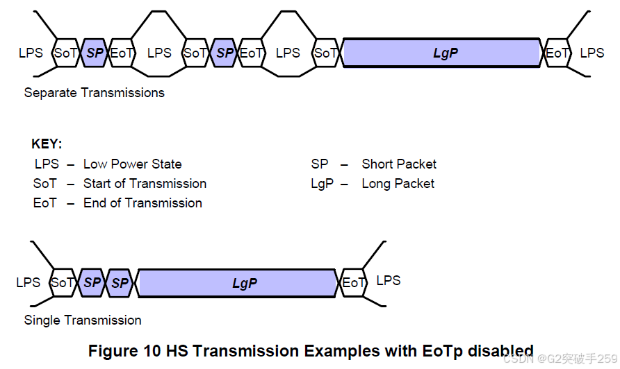 The following figure shows a case of HS transmission generated by EoTp. The short EoT packet is highlighted in red. The chart above illustrates the case where the host intends to send a short packet followed by a long packet using two separate transmissions. In this case, an additional EoT short packet is generated before the end of each transmission. This mechanism provides a more robust environment compared to the case where EoTp generation is disabled, at the cost of increased overhead (an additional four bytes per transmission), where the system relies solely on the physical layer EoT sequence to signal the end of HS transmission. The overhead introduced by enabling EoTp can be minimized by sending multiple long and short packets in a single transmission.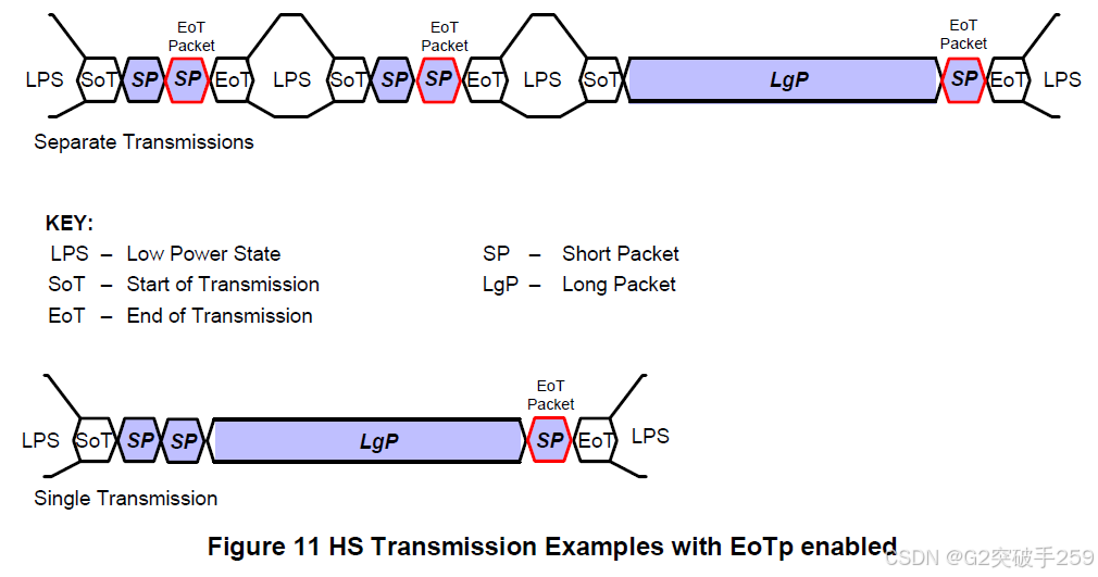
Packet Composition
The first byte of a packet is the Data Identifier (DI), which contains information specifying the type of packet. For example, in a display application in Video Mode, the logical unit of the packet can be a horizontal display line. The Command Mode system sends commands and a set of related parameters, with the number of parameters depending on the command type.Packet sizes are divided into two categories:
- Short packets have a length of 4 bytes, including ECC. Most Command Mode commands and related parameters use short packets. Other short packets convey events such as H Sync and V Sync edges. Because they are short packets, they can pass accurate timing information to the logic of the peripheral.
- Long packets use a two-byte Word Count field to specify the payload length. The payload can range from 0 to 2^16-1 bytes. Therefore, a long packet can be up to 65,541 bytes in length. Long packets allow for the transmission of large blocks of pixels or other data.
One special case of Command Mode operation is the video rate (update) stream, which transmits an arbitrary length pixel stream or other data stream to the peripheral. Since all DSI transactions use packets, the video stream should be broken down into individual packets. This “packaging” can be done by hardware or software. The peripheral can then reassemble these packets into a continuous video stream for display.The Set Maximum Return Packet Size command allows the host processor to limit the size of response packets from the peripheral.
Byte Order Policy
All packet data is transmitted in bytes through the interface. The sender transmits LSB data first, followed by MSB data. For packets with multi-byte fields, unless otherwise specified, the least significant byte should be transmitted first.The following figure shows a complete long packet data transmission. Note that the figure displays byte values in standard positional notation, with MSB on the left and LSB on the right, while bits are displayed in chronological order, with LSB on the left and MSB on the right, with time increasing from left to right.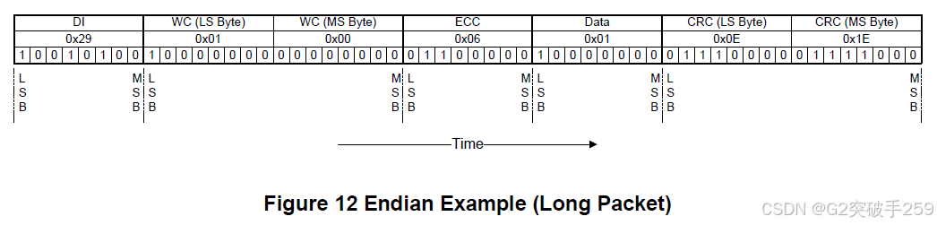
General Packet Structure
Two packet structures are defined for underlying protocol communication: long packets and short packets. For both packet structures, the Data Identifier (DI) is always the first byte of the packet.Long Packet FormatThe following figure shows the structure of a packet. A long packet should consist of three elements: a 32-bit Packet Header (PH), a variable number of application-specific data payload bytes, and a 16-bit Packet Footer (PF). The packet header further consists of three elements: an 8-bit Data Identifier (DI), a 16-bit Word Count (WC), and an 8-bit ECC. The packet footer contains one element, a 16-bit checksum (CRC). The length of a long packet is 6 to 65535 bytes.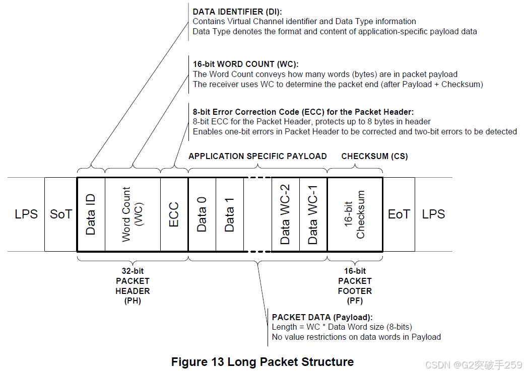 The Data Identifier (DI) defines the virtual channel for the data and specifies the data type for the application-specific payload data.The Word Count (WC) defines the number of bytes in the data payload between the end of the packet header and the start of the packet footer. The packet header and footer are not included in the word count.The Error Correction Code (ECC) byte allows for the correction of single-bit errors and detection of two-bit errors in the packet header. This includes the Data Identifier and Word Count fields.After the packet header ends, the receiver reads the next Word Count * bytes of the data payload. There are no restrictions on the values of the data words in the data payload, i.e., no embedded codes are used.Once the receiver has read the data payload, it will read the checksum in the packet footer. The host processor should always calculate and transmit the checksum in the packet footer. The calculation of the checksum does not require the peripheral. It is also worth noting the special case of zero-byte data payload: if the payload length is 0, the checksum calculation result is (0xFFFF). If the checksum is not calculated, the packet footer should consist of two bytes of all zeros (0x0000).In general, the length of the data payload should be a multiple of bytes. Additionally, each data format may impose additional restrictions on the length of the payload data, such as being a multiple of four bytes.Each byte should first transmit the least significant bit. The payload data can be transmitted in any byte order limited only by the data format requirements. Multi-byte elements such as the Word Count and checksum should be transmitted with the least significant byte first.Short Packet FormatThe following figure shows the structure of a packet. A short packet should contain an 8-bit Data Identifier (DI), followed by two command or data bytes and an 8-bit ECC; the packet footer should not exist. The length of a short packet should be 4 bytes.The Error Correction Code (ECC) byte allows for the correction of single-bit errors and detection of two-bit errors in short packets.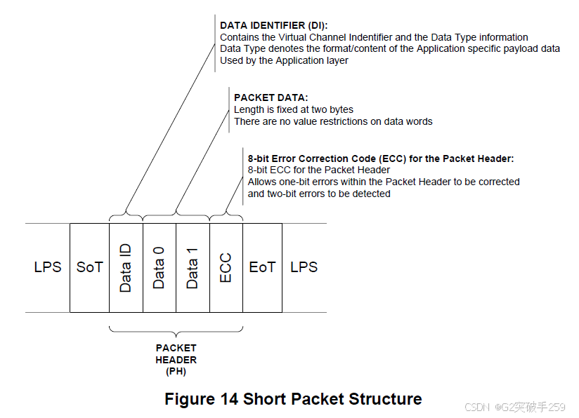
Common Packet Elements
Long packets and short packets share several common elements described in this section.Data Identifier ByteThe first byte of any packet is the Data Identifier (DI) byte. The following figure identifies the composition of the DI byte.DI [7:6]: These two bits identify which of the four virtual channels the data is directed to.DI [5:0]: These 6 bits specify the data type.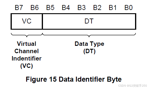 Virtual Channel Identifier – VC Field, DI [7:6]A processor can serve up to four peripherals with labeled commands or data blocks, using the virtual channel ID field in the packet header for different peripherals.The virtual channel ID allows a serial stream to service two or more virtual peripherals by multiplexing packets onto a common transport channel. Note that each packet sent in a single transmission has its own virtual channel assignment and can be directed to different peripherals. Although the DSI protocol allows communication with multiple peripherals, the specification only addresses the connection between the host processor and a single peripheral. The implementation details for connecting to multiple physical peripherals are beyond the scope of this document.Data Type Field DT [5:0]The data type field specifies whether the packet is a long or short packet type and the packet format. The Data Type field, along with the Word Count field of long packets, informs the receiver how many bytes are expected in the remainder of the packet. This is necessary because there are no special packet start/end synchronization codes to indicate the beginning and end of a packet. This allows packets to transmit arbitrary data, but it also requires the packet header to explicitly specify the size of the packet.When the receiving logic has counted down to the end of a packet, it should assume that the next data is either the header of a new packet or an EoT (End of Transmission) sequence.Error Correction CodeThe error correction code allows for the correction of single-bit errors and detection of two-bit errors in the packet header. The main processor should always calculate and transmit an ECC byte. The peripheral should support ECC in both forward and reverse communication.
Cross Data Flow
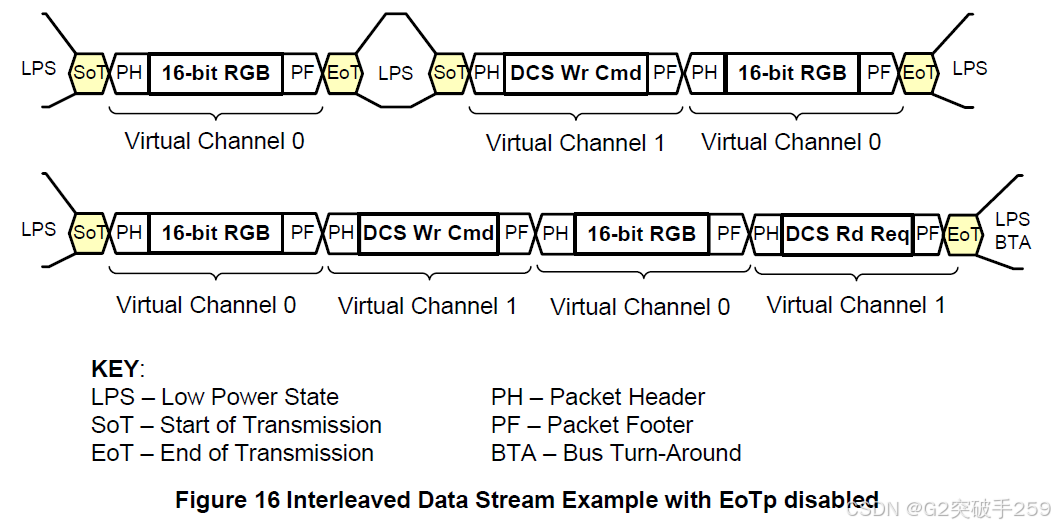 One application of multi-channel is the use of two or more independent driver ICs on a single display module for high-resolution displays. Each driver IC addresses only a portion of the columns on the display device. Each driver IC captures and displays only the packet content intended for that driver, ignoring other packets.
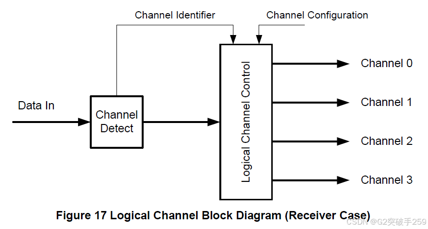 Cross Data Flow and BidirectionalityWhen multiple peripherals have bidirectional capabilities, there should be a clear and unambiguous method to return READ data, events, and status from the intended peripheral to the host processor. The combination of BTA and virtual channel ID ensures that there is no confusion about which peripheral should respond to any request from the peripheral. The returned packet should be tagged with the ID of the peripheral that sent the packet.The result of bidirectionality is that any transmission from the host processor should not contain more than one packet requiring a response from the peripheral. This applies to the number of peripherals connected to the host processor via the Link.
Recommended Articles
|
|||
|
|||
|

Niuxin Semiconductor (Shenzhen) Co., Ltd. (referred to as “Niuxin Semiconductor”) was established in 2020, focusing on the development and licensing of interface IP, and providing related overall solutions, aiming to become a global leading IP supplier.
Niuxin Semiconductor lays out SerDes, DDR, and other mid-to-high-end interface IP in mainstream advanced processes, with products widely used in consumer electronics, network communication, data storage, artificial intelligence, automotive electronics, medical electronics, and other fields.
In the future, Niuxin Semiconductor will continue to respond to the demands of the IP market, adapt to the evolving interface technologies and increasingly expanding interface interconnection scenarios, empowering various industries in the intelligent era.