Follow+Star PublicAccount to not miss exciting contentSource Material | Network
In the early days, microcontrollers had limited performance and resources, making object-oriented programming a “luxury.” Today, with improved performance and resources, object-oriented programming has become a trend.
Today, we will discuss the concepts of object-oriented programming in conjunction with examples of driving LCDs.
Overview of LCD Types
Before discussing how to write an LCD driver, let’s first understand the commonly used embedded LCDs. We will outline some concepts related to driver architecture design without delving into principles and details, which will be covered in dedicated articles or referenced in online documents.
TFT LCD
TFT LCD, commonly referred to as color screens, typically have high pixel counts, such as the common 2.8-inch screen with 320X240 pixels or a 4.0-inch screen with 800X400 pixels. These screens usually use parallel interfaces, specifically the 8080 or 6800 interface (STM32’s FSMC interface); or RGB interfaces supported by chips like STM32F429. Other interfaces, such as MIPI, are used in mobile phones.
In summary, there are many types of interfaces. Some also support SPI interfaces.Unless it is a relatively small screen, using SPI is not recommended due to its slow speed and screen flickering. Common TFT LCD driver ICs used with STM32 include: ILI9341/ILI9325, etc.
COG LCD
Many may not know what COG LCD is; I believe this relates to the current trend in development board sales, where everyone is focusing on large screens and flashy interfaces, neglecting deeper technologies such as software architecture design. COG LCDs actually account for a significant portion of products using microcontrollers.COG stands for Chip On Glass, meaning the driver chip is directly bonded to the glass, making it transparent.
This type of LCD typically has lower pixel counts, commonly 128X64 or 128X32. Generally, it only supports monochrome displays, although grayscale screens are also available.
Interfaces are usually SPI or I2C. There are claims of supporting 8-bit parallel interfaces, but they are rarely used; three IO pins can solve the problem without needing eight. Common driver ICs include: STR7565.
OLED LCD
Those who have purchased development boards have likely used OLEDs. This new technology is perceived as high-end and is commonly used in products like wristbands. Currently, OLED screens are relatively small, and larger ones are quite expensive. In terms of control, they are similar to COG LCDs, with the main difference being their display methods. From a programming perspective, the biggest difference is that OLED LCDs do not require backlight control. The physical object is shown below:
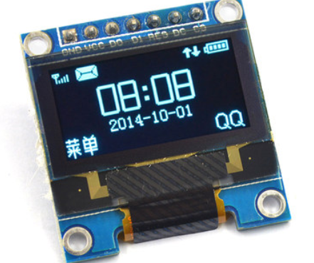
Common interfaces are SPI and I2C. Common driver ICs include: SSD1615.
Hardware Scenarios
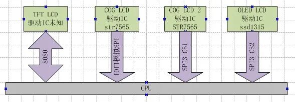
The following discussions are based on the following hardware information:
1. A TFT screen connected to the hardware’s FSMC interface; the model of the screen is unknown.
2. A COG LCD connected to several ordinary IO pins, with the driver IC being STR7565, 128X32 pixels.
3. A COG LCD connected to hardware SPI3 and several IO pins, with the driver IC being STR7565, 128×64 pixels.
4. An OLED LCD connected to SPI3, using CS2 to control chip selection, with the driver IC being SSD1315.
Prerequisite Knowledge
Before we dive into the discussion, let’s briefly cover the following concepts. If you want to delve deeper into these concepts, please GOOGLE them.
Object-Oriented Programming
Object-oriented programming is a concept in the programming world. What does object-oriented mean? Programming has two elements:methods (functions) and data (attributes). For example, an LED can be turned on or off, which is a method. What is the state of the LED? On or off? That is the attribute. We usually program like this:
u8 ledsta = 0;
void ledset(u8 sta)
{
}
However, there is a problem with this approach: if we have 10 such LEDs, how do we write the code? At this point, we can introduce object-oriented programming by encapsulating each LED as an object. We can do it like this:
/*
Define a structure to encapsulate the properties and methods of the LED object.
This structure is an object.
However, this is not a real existence, but an abstraction of an object.
*/
typedef struct {
    u8 sta;
    void (*setsta)(u8 sta);
} LedObj;

/* Declare an LED object named LED1 and implement its method drv_led1_setsta */
void drv_led1_setsta(u8 sta)
{
}

LedObj LED1 = {
        .sta = 0,
        .setsta = drv_led1_setsta,
};

/* Declare an LED object named LED2 and implement its method drv_led2_setsta */
void drv_led2_setsta(u8 sta)
{
}

LedObj LED2 = {
        .sta = 0,
        .setsta = drv_led2_setsta,
};

/* Function to operate on LEDs, parameter specifies which LED */
void ledset(LedObj *led, u8 sta)
{
    led->setsta(sta);
}
Indeed, in C language, the means to achieve object-oriented programming is through the use of structures. The above code is very friendly for APIs. To operate all LEDs, we use the same interface and only need to specify which LED to operate. Consider the earlier mentioned LCD hardware scenarios. For four LCDs, if we do not use object-oriented programming,“wouldn’t we need to implement four interfaces for displaying Chinese characters?” Each screen would have one?
Separation of Driver and Device
If you want to understand the separation of driver and device in depth, please refer to books on LINUX drivers.
What is a device? I believe a device is“attributes”, which are“parameters”, which are“data and hardware interface information used by the driver program”. The driver is the“code process that controls these data and interfaces”.
Generally, if the LCD driver ICs are the same, the same driver can be used. Some different ICs can also use the same driver, for example, SSD1315 and STR7565 can use the same driver except for initialization. For example, a COG LCD:
❝
The driver IC is STR7565, 128 * 64 pixels using SPI3, backlight using PF5, command line using PF4, reset pin using PF3
❞
All the above information combined constitutes a device. The driver is the driver code for STR7565.
Why separate the driver and device? To solve the following problem:
❝
There is a new product, a cash register device. The system has two LCDs, both OLED, with the same driver IC, but one is 128×64 and the other is 128×32 pixels. One is called the main display for the cashier; the other is called the customer display for showing the amount.
❞
This problem can be best solved by“using the same program to control both devices”. The means of separating the driver and device is:
❝
By adding device parameters to the driver program interface function parameters, all resources used by the driver are passed in from the device parameters.
❞
How does the driver bind to the device? Through the model of the device’s driver IC.
Modularity
I believe modularity is about encapsulating a piece of code and providing a stable interface for different drivers to use. Non-modularity means implementing this piece of code in different drivers. For example, in font processing, when displaying Chinese characters, we need to find the dot matrix; when printing Chinese characters on a printer, we also need to find the dot matrix. How do you think the code should be written? Making the dot matrix processing a module is modularity. A typical feature of non-modularity is“a single line running through without any sense of hierarchy”.
What is LCD?
Earlier, we discussed object-oriented programming; now we need to abstract the LCD to derive an object, which requires understanding what an LCD really is. Ask yourself the following questions:
- What can an LCD do?
- What do we want the LCD to do?
- Who wants the LCD to do what?
Friends who are new to embedded systems may not understand this and may find it confusing. Let’s simulate the data flow of LCD functionality operations. The APP wants to display a Chinese character on the LCD.
1. First, we need an interface to display Chinese characters, which the APP can call to display the character, assuming the interface is called lcd_display_hz.
2. Where do the Chinese characters come from? From the dot matrix font library, so within the lcd_display_hz function, we need to call a function called find_font to obtain the dot matrix.
3. After obtaining the dot matrix, we need to display it on the LCD, so we call an interface called ILL9341_dis to refresh the dot matrix on the LCD with the driver IC model ILI9341.
4. How does ILI9341_dis display the dot matrix? By calling an interface called 8080_WRITE.
Okay, this is the general process. We abstract the LCD functional interface from this process. Are Chinese characters related to the LCD object? No. In the eyes of the LCD, whether it is a Chinese character or an image, it is just a series of dots. Therefore, the answers to the earlier questions are:
- The LCD can display content dot by dot.
- To display Chinese characters or images on the LCD—it’s just displaying a bunch of dots.
- The APP wants the LCD to display images or text.
The conclusion is: the function of all LCD objects is to display dots.“Therefore, the driver only needs to provide an interface for displaying dots, whether displaying a single dot or a group of dots.” The abstract interface is as follows:
/*
LCD driver definition
*/
typedef struct
{
    u16 id;

    s32 (*init)(DevLcd *lcd);
    s32 (*draw_point)(DevLcd *lcd, u16 x, u16 y, u16 color);
    s32 (*color_fill)(DevLcd *lcd, u16 sx,u16 ex,u16 sy,u16 ey, u16 color);
    s32 (*fill)(DevLcd *lcd, u16 sx,u16 ex,u16 sy,u16 ey,u16 *color);
    s32 (*onoff)(DevLcd *lcd, u8 sta);
    s32 (*prepare_display)(DevLcd *lcd, u16 sx, u16 ex, u16 sy, u16 ey);
    void (*set_dir)(DevLcd *lcd, u8 scan_dir);
    void (*backlight)(DevLcd *lcd, u8 sta);
}_lcd_drv;
The above interface corresponds to the driver and includes a driver ID number.
- id, driver model
- initialization
- draw point
- display a region of points in a certain color
- display a region of points in certain colors
- display on/off
- prepare refresh area (mainly for color screens using direct DMA refresh)
- set scan direction
- backlight control
Displaying characters, drawing lines, etc., do not belong to the LCD driver. They should be classified under the GUI layer.
LCD Driver Framework
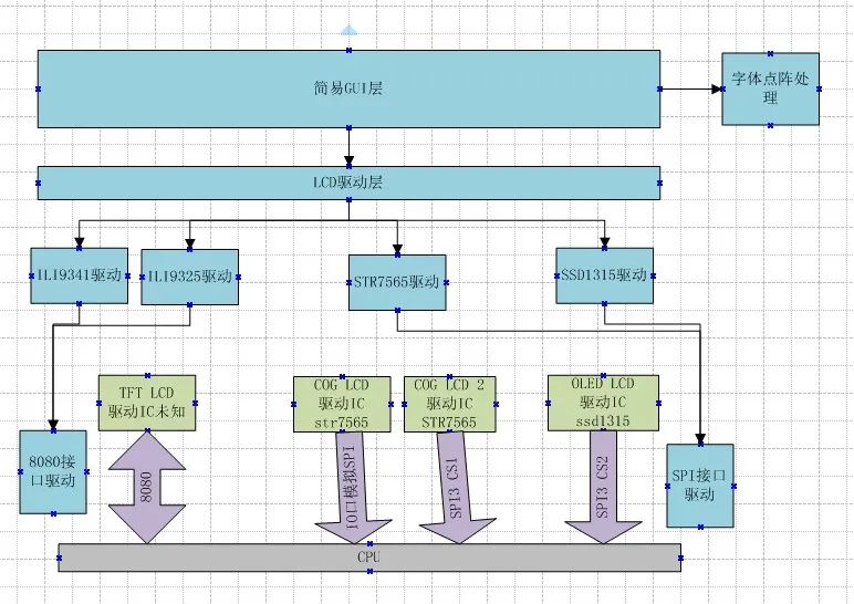
We designed the following driver framework:
Design considerations:
1. The intermediate display driver IC driver program provides a unified interface, structured as the _lcd_drv structure mentioned earlier.
2. Each display IC driver calls different interface drivers based on device parameters. For example, TFT uses 8080 drivers, while others use SPI drivers. There is only one SPI driver, and we also simulate SPI for those controlled by IO pins.
3. The LCD driver layer manages LCDs, such as completing the identification of TFT LCDs, and encapsulates all LCD interfaces into a set of interfaces.
4. The simple GUI layer encapsulates some display functions, such as drawing lines and displaying characters.
5. The font dot matrix module provides interfaces for obtaining and processing dot matrices.
Since it is not as complex in practice, in the example, we combined the GUI and LCD driver layers. The two drivers for TFT LCDs are also placed in one file, but the logic is separated. The OLED, except for initialization, has interfaces that are basically the same as COG LCD, so these two drivers are also placed in one file.
Code Analysis
The code is divided into three layers:
1. GUI and LCD driver layer: dev_lcd.c dev_lcd.h
2. Display driver IC layer: dev_str7565.c & dev_str7565.h dev_ILI9341.c & dev_ILI9341.h
3. Interface layer: mcu_spi.c & mcu_spi.h stm324xg_eval_fsmc_sram.c & stm324xg_eval_fsmc_sram.h
GUI and LCD Layer
This layer mainly has three functions:
1. Device Management
First, a series of LCD parameter structures are defined, containing ID and pixel information. These structures are then combined into a list array.
/* Various LCD specification parameters */
_lcd_pra LCD_IIL9341 = {
        .id   = 0x9341,
        .width = 240,   // LCD width
        .height = 320,  // LCD height
};
...
/* Various LCD list */
_lcd_pra *LcdPraList[5] = {
                &LCD_IIL9341,
                &LCD_IIL9325,
                &LCD_R61408,
                &LCD_Cog12864,
                &LCD_Oled12864,
};
Then, all driver list arrays are defined, with the contents being the drivers implemented in the corresponding driver files.
/* All driver lists */
_lcd_drv *LcdDrvList[] = {
                    &TftLcdILI9341Drv,
                    &TftLcdILI9325Drv,
                    &CogLcdST7565Drv,
                    &OledLcdSSD1615rv,
};
A device tree is defined, indicating how many LCDs the system has, which interface they are connected to, and what driver IC they use. In a complete system, this could be structured like a LINUX device tree.
/* Device tree definition */
#define DEV_LCD_C 3 // The system has 3 LCD devices
LcdObj LcdObjList[DEV_LCD_C] = {
    {"oledlcd", LCD_BUS_VSPI, 0X1315},
    {"coglcd", LCD_BUS_SPI,  0X7565},
    {"tftlcd", LCD_BUS_8080, NULL},
};
2. Interface Encapsulation
void dev_lcd_setdir(DevLcd *obj, u8 dir, u8 scan_dir)
s32 dev_lcd_init(void)
DevLcd *dev_lcd_open(char *name)
s32 dev_lcd_close(DevLcd *dev)
s32 dev_lcd_drawpoint(DevLcd *lcd, u16 x, u16 y, u16 color)
s32 dev_lcd_prepare_display(DevLcd *lcd, u16 sx, u16 ex, u16 sy, u16 ey)
s32 dev_lcd_display_onoff(DevLcd *lcd, u8 sta)
s32 dev_lcd_fill(DevLcd *lcd, u16 sx,u16 ex,u16 sy,u16 ey,u16 *color)
s32 dev_lcd_color_fill(DevLcd *lcd, u16 sx,u16 ex,u16 sy,u16 ey,u16 color)
s32 dev_lcd_backlight(DevLcd *lcd, u8 sta)
Most interfaces are secondary encapsulations of the driver IC interfaces. The initialization and opening interfaces are different. Initialization involves finding the corresponding driver based on the previously defined device tree, locating the corresponding device parameters, and completing device initialization. The open function searches for the device based on the provided device name and returns the device handle, which is required for all subsequent operations.
3. Simple GUI Layer
The most important function currently is the character display function.
s32 dev_lcd_put_string(DevLcd *lcd, FontType font, int x, int y, char *s, unsigned colidx)
Other functions for drawing lines and circles are currently just tests and will be improved later.
Driver IC Layer
The driver IC layer is divided into two parts:
1. Encapsulating LCD Interfaces
LCDs use either the 8080 bus or the SPI bus, and these bus functions are implemented in separate files. However, in addition to these communication signals, LCDs also have reset signals, command data line signals, backlight signals, etc. We encapsulate these signals along with the communication interfaces into“LCD communication bus”, which is buslcd. BUS_8080 is encapsulated in the dev_ILI9341.c file. BUS_LCD1 and BUS_lcd2 are encapsulated in dev_str7565.c.
2. Driver Implementation
Implement the _lcd_drv driver structure. Each driver implements one, and some drivers can share functions.
_lcd_drv CogLcdST7565Drv = {
                            .id = 0X7565,

                            .init = drv_ST7565_init,
                            .draw_point = drv_ST7565_drawpoint,
                            .color_fill = drv_ST7565_color_fill,
                            .fill = drv_ST7565_fill,
                            .onoff = drv_ST7565_display_onoff,
                            .prepare_display = drv_ST7565_prepare_display,
                            .set_dir = drv_ST7565_scan_dir,
                            .backlight = drv_ST7565_lcd_bl
};
Interface Layer
The 8080 layer is relatively simple, using the official interface. The SPI interface provides the following operation functions, which can operate SPI as well as VSPI.
extern s32 mcu_spi_init(void);
ext s32 mcu_spi_open(SPI_DEV dev, SPI_MODE mode, u16 pre);
ext s32 mcu_spi_close(SPI_DEV dev);
ext s32 mcu_spi_transfer(SPI_DEV dev, u8 *snd, u8 *rsv, s32 len);
ext s32 mcu_spi_cs(SPI_DEV dev, u8 sta);
As for why the SPI is written this way, there will be a separate file explaining it.
Overall Process
How are the several modules mentioned earlier connected? Please see the structure below:
/* During initialization, it will be defined based on the number of devices,
    and match the driver with parameters, and initialize variables.
    When opening, it only retrieves a pointer */
struct _strDevLcd
{
    s32 gd; // Handle, controls whether it can be opened

    LcdObj   *dev;
    /* LCD parameters, fixed, unchangeable */
    _lcd_pra *pra;

    /* LCD driver */
    _lcd_drv *drv;

    /* Variables needed by the driver */
    u8  dir;    // Control for landscape or portrait: 0 for portrait; 1 for landscape.
    u8  scandir; // Scan direction
    u16 width;  // LCD width
    u16 height; // LCD height

    void *pri; // Private data, black and white screens and OLED screens will allocate display memory during initialization
};
Each device will have such a structure, which is initialized when the LCD is initialized.
- The member dev points to the device tree, from which the device name, which LCD bus it is connected to, and the device ID can be known.
typedef struct
{
    char *name; // Device name
    LcdBusType bus; // Connected to which LCD bus
    u16 id;
} LcdObj;
- The member pra points to the LCD parameters, which can provide information about the LCD specifications.
typedef struct
{
    u16 id;
    u16 width;  // LCD width  portrait
    u16 height; // LCD height    portrait
}_lcd_pra;
- The member drv points to the driver, and all operations are implemented through drv.
typedef struct
{
    u16 id;

    s32 (*init)(DevLcd *lcd);

    s32 (*draw_point)(DevLcd *lcd, u16 x, u16 y, u16 color);
    s32 (*color_fill)(DevLcd *lcd, u16 sx,u16 ex,u16 sy,u16 ey, u16 color);
    s32 (*fill)(DevLcd *lcd, u16 sx,u16 ex,u16 sy,u16 ey,u16 *color);

    s32 (*prepare_display)(DevLcd *lcd, u16 sx, u16 ex, u16 sy, u16 ey);

    s32 (*onoff)(DevLcd *lcd, u8 sta);
    void (*set_dir)(DevLcd *lcd, u8 scan_dir);
    void (*backlight)(DevLcd *lcd, u8 sta);
}_lcd_drv;
- The members dir, scandir, width, and height are common variables used by the driver. Since each LCD has a structure, a set of driver programs can control multiple devices without interference.
- The member pri is a private pointer; some drivers may require special variables, which are all recorded using this pointer. Typically, this pointer points to a structure defined by the driver, and memory space is allocated during device initialization. Currently, it is mainly used for display buffers for COG LCD and OLED LCD.
The entire LCD driver is combined through this structure.
1. During initialization, based on the device tree, find the driver and parameters, and then initialize the structure mentioned above.
2. Before using the LCD, call the dev_lcd_open function. If successful, it returns a pointer to the structure mentioned above.
3. To display characters, the interface finds the dot matrix and calls the corresponding driver program through the drv of the above structure.
4. The driver program decides which LCD bus to operate based on this structure and uses the variables of this structure.
Usage and Benefits
- Benefit 1
Please see the test program
void dev_lcd_test(void)
{
    DevLcd *LcdCog;
    DevLcd *LcdOled;
    DevLcd *LcdTft;

    /* Open three devices */
    LcdCog = dev_lcd_open("coglcd");
    if(LcdCog == NULL)
        uart_printf("open cog lcd err\r\n");

    LcdOled = dev_lcd_open("oledlcd");
    if(LcdOled == NULL)
        uart_printf("open oled lcd err\r\n");

    LcdTft = dev_lcd_open("tftlcd");
    if(LcdTft == NULL)
        uart_printf("open tft lcd err\r\n");

    /* Turn on backlight */
    dev_lcd_backlight(LcdCog, 1);
    dev_lcd_backlight(LcdOled, 1);
    dev_lcd_backlight(LcdTft, 1);

    dev_lcd_put_string(LcdOled, FONT_SONGTI_1212, 10, 1, "ABC-abc,", BLACK);
    dev_lcd_put_string(LcdOled, FONT_SIYUAN_1616, 1, 13, "这是oled lcd", BLACK);
    dev_lcd_put_string(LcdOled, FONT_SONGTI_1212, 10, 30, "www.wujique.com", BLACK);
    dev_lcd_put_string(LcdOled, FONT_SIYUAN_1616, 1, 47, "屋脊雀工作室", BLACK);

    dev_lcd_put_string(LcdCog, FONT_SONGTI_1212, 10, 1, "ABC-abc,", BLACK);
    dev_lcd_put_string(LcdCog, FONT_SIYUAN_1616, 1, 13, "这是cog lcd", BLACK);
    dev_lcd_put_string(LcdCog, FONT_SONGTI_1212, 10, 30, "www.wujique.com", BLACK);
    dev_lcd_put_string(LcdCog, FONT_SIYUAN_1616, 1, 47, "屋脊雀工作室", BLACK);

    dev_lcd_put_string(LcdTft, FONT_SONGTI_1212, 20, 30, "ABC-abc,", RED);
    dev_lcd_put_string(LcdTft, FONT_SIYUAN_1616, 20, 60, "这是tft lcd", RED);
    dev_lcd_put_string(LcdTft, FONT_SONGTI_1212, 20, 100, "www.wujique.com", RED);
    dev_lcd_put_string(LcdTft, FONT_SIYUAN_1616, 20, 150, "屋脊雀工作室", RED);

    while(1);
}
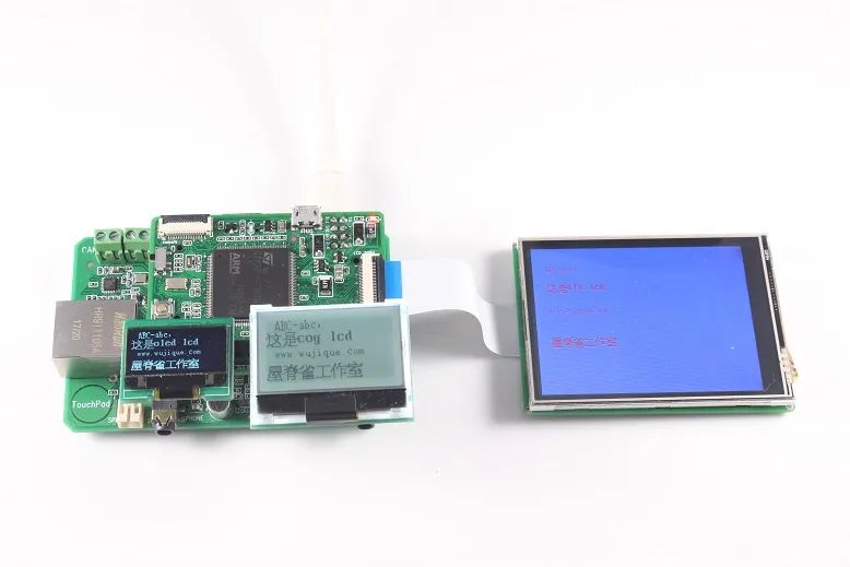
Using a single function dev_lcd_open, we can open three LCDs and obtain the LCD devices. Then, calling dev_lcd_put_string allows us to display on different LCDs. All other GUI operation interfaces are unified. This design is very user-friendly for the APP layer. The display effect is shown below:
- Benefit 2
The current device tree is defined as follows:
LcdObj LcdObjList[DEV_LCD_C] =
{
    {"oledlcd", LCD_BUS_VSPI, 0X1315},
    {"coglcd", LCD_BUS_SPI,  0X7565},
    {"tftlcd", LCD_BUS_8080, NULL},
};
One day, if the OLED LCD needs to be connected to SPI, we only need to change the parameters in the device tree array, of course, two devices cannot be connected to one interface.
LcdObj LcdObjList[DEV_LCD_C] =
{
    {"oledlcd", LCD_BUS_SPI, 0X1315},
    {"tftlcd", LCD_BUS_8080, NULL},
};
Font Library
Currently, the font library in the example is stored on an SD card, and you can modify it according to your needs during porting. Please refer to font.c for specifics.
Disclaimer
This method is for learning programming ideas and techniques and may not be suitable for all projects.
Disclaimer:This article’s material is sourced from the internet, and the copyright belongs to the original author. If there are any copyright issues, please contact me for removal.
———— END ————

● Column “Embedded Tools”
● Column “Embedded Development”
● Column “Keil Tutorials”
● Selected Tutorials in Embedded Column
Follow the public account Reply “Add Group” to join the technical exchange group according to the rules, reply “1024” to see more content.
Click “Read the original text” to see more shares.