
How to Learn Mechanical Drawing? It Would Be Too Difficult Without These Materials!
(Click on the above brown text to download the materials)
In engineering, the RS485 control line is often mentioned. What exactly is it? Today, I will discuss the applications related to RS485. By delving into RS485, you will find that there is indeed a lot of knowledge involved. We will choose some common issues in low voltage systems for everyone to understand.
1. What is RS485 Bus?
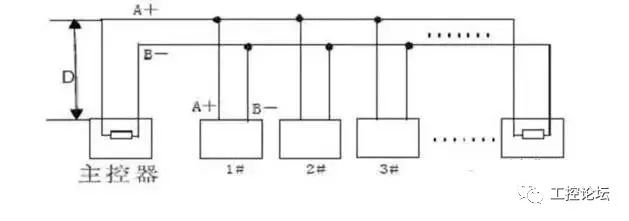
In industrial sites, data from multiple points is often collected, whether it be analog signals or switch signals. Generally, the RS485 bus is used, which operates in half-duplex mode and supports multipoint data communication. The RS-485 bus network topology typically adopts a terminal-matched bus structure. This means that a single bus connects all nodes in series, and it does not support ring or star networks.
RS485 does not have a specific physical shape; it uses interfaces depending on the actual engineering situation. RS485 uses differential signaling with negative logic, where +2V to +6V represents “0” and -6V to -2V represents “1”.
RS485 can be wired in two-wire or four-wire configurations. The four-wire configuration only allows point-to-point communication and is rarely used now. The two-wire configuration is more commonly adopted, allowing up to 32 nodes to be connected on the same bus topology.
The communication distance of the RS485 bus can reach 1200 meters. According to the theoretical structure of the RS485 bus, under ideal conditions, the transmission distance can reach 1200 meters. This condition requires high-quality communication cables, a baud rate of 9600, and only one RS485 device loaded to achieve this distance. Therefore, the actual stable communication distance of the RS485 bus often does not reach 1200 meters. If multiple RS485 devices are loaded, if the cable impedance does not meet standards, if the wire gauge is too small, if the converter quality is poor, or if complex lightning protection is required, and with an increase in baud rate, these factors will all reduce the communication distance.
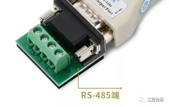
2. RS485 Cable
In general situations, ordinary twisted pairs can be used. In environments with higher requirements, shielded coaxial cables can be used. When using the RS485 interface, for specific transmission lines, the maximum cable length allowed for data signal transmission from the RS485 interface to the load is inversely proportional to the signal transmission baud rate. This length is mainly affected by signal distortion and noise.
Theoretically, the maximum transmission distance of RS485 can reach 1200 meters, but in practical applications, the transmission distance is usually shorter than 1200 meters, depending on the surrounding environment. During transmission, repeaters can be used to amplify the signal, with a maximum of eight repeaters allowed, meaning the theoretical maximum transmission distance of RS485 can reach 9.6 kilometers. If long-distance transmission is truly needed, optical fiber can be used as the transmission medium, with a photoelectric converter added at each end. The transmission distance of multimode fiber is 5-10 kilometers, while single-mode fiber can reach a transmission distance of 50 kilometers.
3. Installation Considerations for RS485 Wiring
1. What type of communication cable should be used for the RS485 bus? How many devices can be connected on one bus?
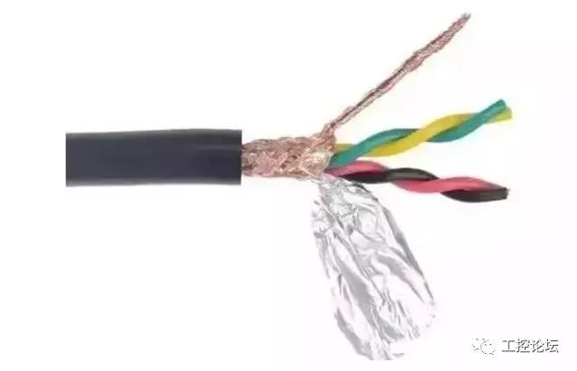
Shielded twisted pair cable must be used. The specifications of the shielded twisted pair cable used are related to the distance of the RS485 communication line and the number of devices connected, as shown in the table below. Using shielded twisted pair cables helps to reduce and eliminate the distributed capacitance generated between the two RS485 communication lines and common-mode interference from the surrounding communication lines.
Some say that the RS485 bus can communicate with 128 devices.
However, not all RS485 converters can support 128 devices; it depends on the model of the chip inside the RS485 converter and the chip model of the RS485 devices. The load capacity can only be determined according to the chip with the lowest specifications. Generally, RS485 chips have three levels of load capacity: 32 devices, 128 devices, and 256 devices. Moreover, the nominal specifications are often not achievable in practice; the longer the communication distance, the higher the baud rate, the thinner the wire gauge, the poorer the quality of the cable, the worse the quality of the converter, and the stronger the lightning protection, all of these factors will reduce the actual load capacity.
Most engineering companies habitually use Category 5 or Category 5e cables as RS485 communication lines, which is incorrect because:
(1. Ordinary network cables do not have shielding and cannot prevent common-mode interference.
(2) Cables with too small a gauge cannot be used, as this will reduce transmission distance and the number of devices that can be connected, at least 0.4 mm² or use standard network cables.
(3) Network cables consist of single copper wires, which are more prone to breakage compared to multi-core wires.
2. Why is grounding necessary?
The RS485 transceiver can only operate normally when the common-mode voltage is between -7V and +12V. Exceeding this range will affect communication, and in severe cases, it can damage the communication interface. Common-mode interference can increase the above common-mode voltage. One effective way to eliminate common-mode interference is to use the shield of the RS485 communication line as a ground wire, connecting the equipment, computers, and other devices in the network to a single reliable ground.
3. How should the RS485 communication lines be routed?
Communication lines should be kept as far away as possible from high-voltage power lines, fluorescent lights, and other sources of interference. If communication lines cannot avoid interference sources, they should be routed perpendicular to power lines, not parallel, and definitely not bundled together, using high-quality twisted pair cables.
4. Why should the RS485 bus adopt a daisy chain structure instead of a star structure?
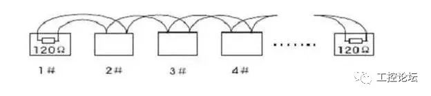
The star structure can cause reflected signals, which can interfere with RS485 communication. The branch line from the bus to each terminal device should be kept as short as possible, generally not exceeding 5 meters. If the branch line is not terminated, it will have reflected signals, causing strong interference in communication. It should be removed, and it is best to connect a 120Ω termination resistor at both ends of the RS485 devices.
Daisy chain connection is shown in the figure:
Star connection is shown in the figure:
5. Can there be junctions between devices on the RS485 bus?
In the same network system, using the same type of cable, try to minimize junctions in the line. Ensure that the junctions are well soldered, tightly wrapped, and avoid looseness and oxidation. Ensure a single, continuous signal channel as the bus.
6. What are common-mode interference and differential-mode interference? How to eliminate interference on communication lines?
The RS485 communication line consists of two twisted wires, which transmit signals through the voltage difference between the two communication lines, thus referred to as differential voltage transmission. Differential-mode interference occurs between the two signal lines and is symmetric interference. The method to eliminate differential-mode interference is to add a bias resistor (matching resistor in the ball machine) in the circuit and use twisted pairs; common-mode interference occurs between the signal line and ground, and it is asymmetric interference. Methods to eliminate common-mode interference include:
(1) Use shielded twisted pairs and ensure proper grounding.
(2) In areas with strong electric fields, consider using galvanized pipe shielding.
(3) During wiring, keep away from high-voltage lines and do not bundle high-voltage power lines with signal lines.
(4) Use linear regulated power supplies or high-quality switching power supplies (ripple interference less than 50mV).
7. Under what circumstances should termination resistors be added to the RS485 bus?
Generally, termination resistors are not needed, only when the RS485 communication distance exceeds 300 meters, should termination resistors be added at the beginning and end of the RS485 communication. Especially when the number of devices on the RS485 bus is small. When the number of devices is large (e.g., over 22 devices), termination resistors are generally not needed, as termination resistors will reduce the load capacity of the RS485 bus. The connection method for the 120Ω matching resistor at the ball machine terminal is as follows: the 120Ω matching resistor can be connected by toggling the dip switch on the bottom of the ball machine. The 120Ω matching resistor is not connected by default when the ball machine is manufactured; it can be connected by toggling the 10th position of the dip switch to ON. Conversely, if the 120Ω matching resistor is not to be connected, toggle the 10th position to OFF.
8. Issues in Practical Applications
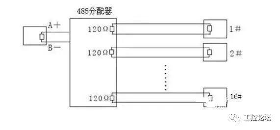
In practical construction, users often adopt star connection methods. In this case, termination resistors must be connected to the two devices that are farthest apart (as shown in the figure, devices 1# and 15#). However, since this connection method does not comply with the industrial standards for RS485, it can easily cause signal reflections, reduced anti-interference ability, and other issues, leading to decreased reliability of control signals. The observed phenomena in this case include the ball machine being completely uncontrollable or operating automatically without stopping.
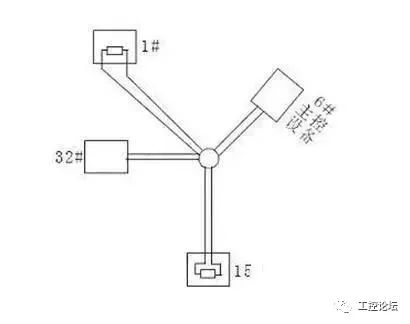
For this situation, it is recommended to add an RS485 distributor. This product can effectively convert star connections into connections that comply with the industrial standards for RS485, thus avoiding problems and improving communication reliability, as shown in the figure below.
9. Recommended Cables for Maximum Transmission Distance Without Repeaters
(1) Ordinary twisted shielded cable STP-120Ω (for RS485 & CAN) one pair 20 AWG, cable outer diameter about 7.7mm. Suitable for indoor, pipeline, and general industrial environments. When using, one end of the shielding layer should be grounded!
(2) Ordinary twisted shielded cable STP-120Ω (for RS485 & CAN) one pair 18 AWG, cable outer diameter about 8.2mm. Suitable for indoor, pipeline, and general industrial environments. When using, one end of the shielding layer should be grounded!
(3) Armored twisted shielded cable ASTP-120Ω (for RS485 & CAN) one pair 18 AWG, cable outer diameter about 12.3mm. Can be used in places with serious interference, frequent rodent damage, and lightning and explosion protection requirements. When using, it is recommended to ground both ends of the armor layer, and the innermost shield should be grounded at one end.
4. Common Faults and Solutions for RS485
1. How to Prevent Faults?
To reduce communication faults, the following suggestions are proposed.
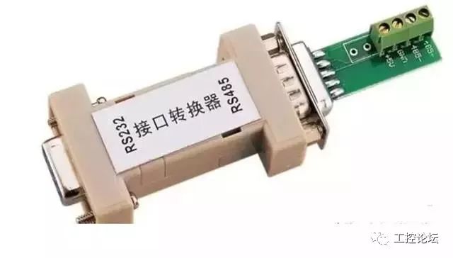
1. It is recommended that users use and purchase RS485 converters provided by the manufacturer or specified brands recommended by the manufacturer.
2. Manufacturers conduct extensive testing on RS485 converters compatible with their products and require RS485 converter manufacturers to produce and quality test according to fixed performance parameters, ensuring good compatibility with access control devices. Do not be tempted to buy cheap converters from lesser-known brands.
3. Strictly follow the construction specifications for RS485 bus wiring, eliminating any sense of complacency.
4. For long lines with many loads, adopt a scientific and reserved solution.
5. If the communication distance is too long, such as exceeding 500 meters, it is recommended to use repeaters or RS485 HUBs to resolve the issue.
6. If the number of loads is too high, such as exceeding 30 devices on one bus, it is recommended to use RS485 HUBs to solve the problem.
7. Bring debugging equipment for on-site debugging. During on-site debugging, be sure to carry several converters that can handle long distances and multiple loads, a commonly used laptop, a multimeter for testing circuit breaks, and several 120-ohm termination resistors.
2. Common Communication Faults in RS485 Bus Structure
1. No communication, no response.
2. Data can be uploaded but cannot be downloaded.
3. During communication, the system prompts interference, or the communication indicator keeps flashing even when not communicating.
4. Sometimes communication works, sometimes it does not; some commands work while others do not.
3. What Debugging Methods Are Available When Faults Occur?
Before debugging, ensure that the device connections are correct and that the construction complies with standards. Depending on the encountered issues, the following debugging methods can be employed.
1. Common Ground Method:
Use one line or shielded cable to connect the GND of all RS485 devices together to avoid potential differences affecting communication.
2. Termination Resistor Method:
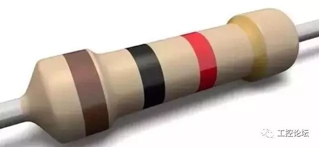
Connect a 120-ohm termination resistor across the 485+ and 485- of the last RS485 device to improve communication quality.
3. Intermediate Segment Disconnection Method:
Check by disconnecting from the middle to see if the device load is too high, the communication distance is too long, or if a certain device is affecting the entire communication line.
4. Single Wire Method:
Individually run a simple wire to the device to determine if wiring is causing communication faults.
5. Converter Replacement Method:
Carry several converters to rule out whether converter quality issues are affecting communication quality.
6. Laptop Debugging Method:
Ensure that the laptop you carry is a device that communicates normally. Use it to replace the customer’s computer for communication; if it works, it indicates that the customer’s computer’s serial port may be damaged or malfunctioning.
In low voltage intelligent engineering, the application of RS485 is widespread, commonly used in access control systems, BA systems, intelligent lighting systems, parking management systems, etc. With the continuous popularization of digital networks, the application of RS485 in low voltage systems is decreasing.
Hurry up and share and save it!
Source:Network
Quality Articles:
Japan: We Never Do Equipment Repair!

Investing 200 Million in R&D, Switzerland's Craziest Liquid Mechanical Watch, This Is How It Was Made

The Ministry of Industry and Information Technology Announces: List of 507 Invisible Champions in China's Manufacturing Industry!

The First Half of the Tank of Oil Lasts Long, the Second Half Disappears in No Time! What Did Sinopec Do in the Oil?

Samsung Shuts Down Kunshan Motor Factory! Employee Compensation N+5!

The U.S. Didn't Stop It? China Successfully Takes Down the Power Tsar..... No Longer Being Suppressed
Boeing 737MAX Series Aircraft Production Halted, Is It a Desperate Measure or Something Else?

Another Giant Falls from Grace, with a Debt of 11.4 Billion! Almost Everyone Has Bought Its Products!

Data Access:

Limited Time Download | 18G Fanuc Robot Video Tutorial (Total 82 Lectures)! Limited Time Free | 71 Sets of Industrial Robot Four Major Families Blueprints/Mechanical Arm Blueprints Available for Free | "Industrial Robot Engineering Application Virtual Simulation Tutorial"


Click for More